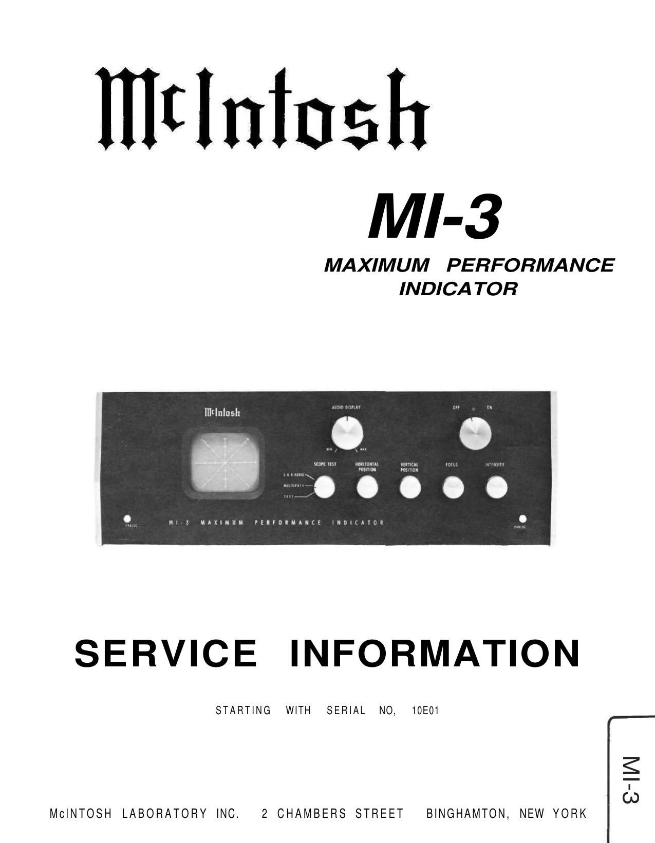
McIntosh MI 3 Service Manual

This is the 5 pages manual for McIntosh MI 3 Service Manual.
Read or download the pdf for free. If you want to contribute, please mail your pdfs to info@audioservicemanuals.com.

Page: 1 / 5
left right
McIntosh MI 3 Service Manual

Extracted text from McIntosh MI 3 Service Manual (Ocr-read)


Page 1

MI-3 SCHEMATIC NOTES AUDIO DRIVER P.C. BOARD 043-984 I. Unless otherwise specified: Resistance values are in ohms, 1/2 watt, and 10% tolerance; capacitance values a re in microfarads (µF). 2 . Printed circuit board components are outlined on the schematics by dotted lines. The circIed numbers around the dotted lines correspond to the numbers on the PC Board layouts. 3. The terminal number ing of rotary switches is for reference only. 4. All voltages indicated on the schema tics are measured under the following conditions: a. Use of an 11 megohm input impedance VTVM. b. All voltages ±10% with respect to chassis ground. c. No signal at input or antenna terminals. d. AC Input at 117 volts, 50/60 Hz. e. Mode selector at test position. 5. In units with Serial No's below 10E26, two neon bulbs (Mclntosh Part No. 058-002) are used in place of R59 - 6. In units with Serial No's from 10E26 to 15E00, R60 and R61 are used. 7. In units with Serial No's below 13E00, a 6W4 rectifier tube (Mclntosh Part No. 165-016) is used in place of SR7 - 8. In early units, PC Board 043-984 and R43 and R50 are not used. The arm of R48A is connected directly to pin No. 2 of S1 and the arm of R48B is connected directly to C7.

Page 2

HORIZONTAL AMPLIFIER AUDIO DRIVER P.C. BOARD 043-984 NOTE 8 VERTICAL AMPLIFIER