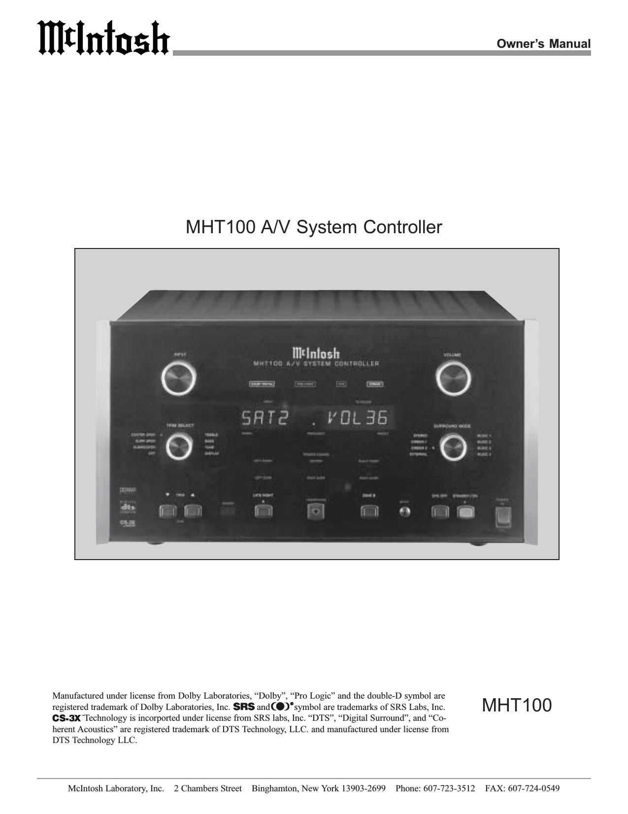
McIntosh MHT 100 Owners Manual

This is the 60 pages manual for McIntosh MHT 100 Owners Manual.
Read or download the pdf for free. If you want to contribute, please mail your pdfs to info@audioservicemanuals.com.

Page: 1 / 60
left right
McIntosh MHT 100 Owners Manual

Extracted text from McIntosh MHT 100 Owners Manual (Ocr-read)


Page 1

2 IMPOR T ANT SAFETY INSTRUCTIONS! PLEASE READ THEM BEFORE OPERATING THIS EQUIPMENT. WARNING - TO REDUCE RISK OF FIRE OR ELECTRICAL SHOCK, DO NOT EXPOSE THIS EQUIPMENT TO RAIN OR MOISTURE. The lightning flash with arrowhead, within an equilateral triangle, is intended to alert the user to the presence of uninsulated dangerous voltage within the products enclosure that may be of sufficient magnitude to constitute a risk of electric shock to persons. NO USER-SERVICEABLE PARTS INSIDE. REFER SERVICING TO QUALIFIED PERSONNEL. To prevent the risk of electric shock, do not remove cover or back. No user serviceable parts inside. The exclamation point within an equi- lateral triangle is intended to alert the user to the presence of important operating and maintenance (servic- ing) instructions in the literature ac- companying the appliance. General: 1. Read these instructions. 2. Keep these instructions. 3. Heed all warnings. 4. Follow all instructions. 5. Warning: To reduce risk of fire or electrical shock, do not expose this equipment to rain or moisture. This unit is capable of producing high sound pres- sure levels. Continued exposure to high sound pres- sure levels can cause permanent hearing impair- ment or loss. User caution is advised and ear protec- tion is recommended when playing at high volumes. 6. Caution: to prevent electrical shock do not use this (polarized) plug with an extension cord, receptacle or other outlet unless the blades can be fully in- serted to prevent blade exposure. Attention: pour pevenir les chocs elecriques pas utiliser cette fiche polarisee avec un prolongateur, une prise de courant ou un autre sortie de courant, sauf si les lames peuvent etre inserees afond ans en laisser aucune partie a decouvert. 7. Unplug this equipment during lightning storms or when unused for long periods of time. 8. Only use attachments/accessories specified by the manufacturer. Installation: 9. The equipment shall be installed near the AC Socket Outlet and the disconnect device shall be easily acces- sible. 10. Do not block any ventilation openings. Install in accor- dance with the manufacturers instructions. 11. Do not install near any heat sources such as radiators, heat registers, stoves, or other equipment (including amplifiers) that produce heat. 12. Do not use this equipment near water. 13. Do not expose this equipment to dripping or splashing and ensure that no objects filled with liquids, such as vases, are placed on the equipment. 14. Use only with the cart, stand, tripod, bracket, or table specified by the manu- facturer, or sold with the equipment. When a cart is used, use caution when moving the cart/equipment combination to avoid injury from tip-over. Connection: 15. Connect this equipment only to the type of AC power source as marked on the unit. 16. Protect the power cord from being walked on or pinched particularly at plugs, convenience receptacles, and the point where they exit from the equipment. 17. Do not defeat the safety purpose of the polarized or grounding-type plug.

Page 2

3 A polarized plug has two blades with one wider than the other. A grounding type plug has two blades and a third grounding prong. The wide blade or the third prong are provided for your safety. If the provided plug does not fit into your outlet, consult an electrician for replacement of the obsolete outlet. 18. Do not overload wall outlets, extension cords or inte- gral convenience receptacles as this can result in a risk of fire or electric shock. 19. To completely disconnect this equipment from the AC Mains, disconnect the power supply cord plug from the AC receptacle. Outdoor Antenna: 20. If an outdoor antenna is connected to the antenna ter- minal, be sure the antenna system is grounded to pro- vide some protection against voltage surges and built up static charge. In the U.S.A., section 810 of the Na- tional Electrical Code, ANSI/NFPA No. 70-1978, pro- vides information on the proper ground for the mast and supporting structure, ground for the lead-in wire to an antenna discharge unit, and size of ground conduc- tors, location of antenna-discharge unit, connection to ground electrode. For ground wire: A. Use No. 10 AWG (5.3 mm 2) copper No. 8 AWG (8.4 mm 2) aluminum, No. 17 AWG (1.0 mm 2) cop- per-clad steel, bronze, or larger as ground wire. B. Secure antenna lead-in and ground wires to the house with stand-off insulators spaced from 4 feet (1.2 meters) to 6 feet (1.83 meters) apart. C. Mount antenna discharge unit as closely as possible to where lead-in enters house.D. Use jumper wire not smaller than No. 6 AWG (13.3 mm 2) copper or equivalent when separate antenna grounding electrode is used. Care of Equipment: 21. Clean only with a dry cloth. 22. Do not permit objects or liquids of any kind to be pushed, spilled and/or fall into the equipment through enclosure openings. 23. Unplug the power cord from the AC power outlet when left unused for a long period of time. Repair of Equipment: 24. Refer all servicing to qualified service personnel. Ser- vicing is required when the equipment has been dam- aged in any way, such as power-supply cord or plug is damaged, liquid has been spilled or objects have fallen into the equipment, the equipment has been exposed to rain or moisture, does not operate normally, or has been dropped. 25. Do not attempt to service beyond that described in the operating instructions. All other service should be re- ferred to qualified service personnel. 26. When replacement parts are required, be sure the ser- vice technician has used replacement parts specified by McIntosh or have the same characteristics as the origi- nal part. Unauthorized substitutions may result in fire, electric shock, or other hazards. 27. Upon completion of any service or repairs to this prod- uct, ask the service technician to perform safety checks to determine that the product is in proper operating condition.

Page 5

6 Connector Information Keypad Terminal Connector To use a WK-3 or WK-4 keypad with the MHT100, con- nect the shield and four leads of a shielded 4 conductor cable to a RJ-45 Connector Plug, according to the numbers listed below. There is a numbered connector built-in to each keypad, which has a different pin out. MHT100 RJ-45 WK-3 and WK-4 Keypad 1. Signal Data 1. Supply Voltage Positive 2. Signal Data Gnd. 2. Supply Voltage Negative and Cable Shield 3. Cable Shield 3. N/C 4. Signal Data 4. Supply Voltage Negative 5. Signal Data Gnd. 5. Supply Voltage Positive 6. N/C 7. N/C 8. N/C RS232 DB9 Connector Pin Layout 1. N/C 6. N/C 2. Data Out (TXD) 7. N/C 3. Data In (RXD) 8. N/C 4. N/C 9. N/C 5. Gnd. RAA1 Connector Connect the shield and two leads of a shielded 2 conductor cable to the supplied 5 Pin Terminal Connector Plug. Refer to the connection infor- mation on the top cover of the RAA1. Power Control Connector The MHT100s Power Control Outputs provide a 12 volt signal. Use a 1/8 inch stereo mini phone plug to connect to the Power Control Input.Data and IR Port Connectors The MHT100s Data Port Output provides Remote Control Signals and the IR Port allows for the connection of other brands IR Sensors. Use a 1/8 inch stereo mini phone plug to connect to the Data Port Inputs on McIntosh Source Units. Note: The MHT100 Rear Panel IR POWER Switch setting determines if twelve volt is present at the Zone A and B IR INPUTS. MHT100 Keypad Socket Red (TV)Black (RF) Green (GND) Positive N/C Ground Data Signal N/C Data Ground Data Port Connector IR Port Connector with Rear Panel IR Power Switch Set to On Data Signal Ground +12Volts Data Signal Ground IR Port Connector with Rear Panel IR Power Switch Set to Off N/C

Page 32

33 Subwoofer Adjustment Default Setting New Setting MC BASS MODE OFF SUB CROSSOVER 80HZ DD LFE LEVEL 0dB Subwoofer Settings made, select YES to save those changes or NO not to save them. The MHT100 will then return to normal op- eration. Refer to figure 13 on page 25. DD LFE Level The Digital Processing Circuitry in the MHT100 allows for a reduction in the overall low frequency output level of the Home Theater System. This desired reduction may be as a result of the Loudspeakers in the systems, the average low frequency level found in the program sources, room acous- tics and/or the need not to disturb person(s) that are nearby the Home Theater Listening Room. The default setting for the DD (Dolby Digital) LFE (Low Frequency Effect) LEVEL setting is 0db and is the correct setting for most Home Theater Systems. Refer to figure 23 and perform the following steps to change the setting. Note: If the overall low frequency output level is reduced by using the DD LFE LEVEL Adjustment and certain program source materials appear to be deficient in low frequency output, they can be increased by using the MHT100 Subwoofer Trim Level Control on the Front Panel or Remote Control. 9. Using the Up or Down directional push-buttons SETUP, cont Figure 23 MENU: SUBWOOFER SETTINGS 1. MC BASS MODE OFF 2. SUB CROSSOVER 80 Hz 3. DD LFE LEVEL 0dB EXIT Figure 22 MENU: SUBWOOFER SETTINGS 1. MC BASS MODE OFF 2. SUB CROSSOVER 80 Hz 3. DD LFE LEVEL 0dB EXIT select DD LFE LEVEL from the On-Screen Menu, fol- lowed by pressing the Left directional push-button to reduce the level. The Right directional push-button increase the level back towards 0dB. Select EXIT on the menu and the MAIN SYSTEM SETUP Menu will reappear on the Monitor/TV screen. 10. Continue next to the SOURCE SETTINGS. If you do not wish to perform SOURCE SETTINGS Adjust- ments at this time, proceed to the next step. 11. Select EXIT from the MAIN SYSTEM SETUP Menu. If you are satisfied with the changes that you may have made, select YES to save those changes or NO not to save them. The MHT100 will then return to normal op- eration. Refer to figure 13 on page 25.

Page 35

36 Source Numbe r De fa ult Input Numbe r De fa ult Input Na me Ne w Input Numbe r Ne w Input Na me 1 I N 3 SA T 2 I N 5 DVD Component Video Source Settings 13. Using the Up or Down directional push-buttons select Number 4 INPUT TRIM on the On-Screen Menu, followed by pressing the Left or Right di- rectional push-buttons to select. 14. Using the Left directional Push-button select -3dB for the new INPUT TRIM Level. Select EXIT on the menu and the MAIN SYSTEM SETUP Menu will re- appear on the Monitor/TV screen. 15. Select EXIT from the MAIN SYSTEM SETUP Menu, select YES to save the changes and the MHT100 will then return to normal operation. 16. Compare the new AUX Input Volume Level to the Tuner Volume Level. If the AUX Input Volume Level is still louder than the Tuner perform the Source Set- ting step 1 and then steps 12 through 16. When the vol- ume level on the AUX Input is about the same as the Tuner Input, perform the Input Trim Adjustments for any other Inputs that are quieter or louder than the Tuner. Component Input The MHT100 has Electronic Input Switching for two Com- ponent Video Sources. The default assignments for the two inputs can be changed to match up with the two Compo- nent Video Sources in your system. The following example describes how to reassign COMPONENT 1 IN Video In- put, which by default has been assigned to SAT Input, over to the VCR1 Input instead. 17. Using the Up or Down directional push-buttons select Number 1 SOURCE INPUT from the On-Screen Menu, followed by pressing the Left or Right di- rectional push-buttons to select the SAT Input, Number 3. Refer to figure 26. 18. Using the Up or Down directional push-buttons select Number 5 COMPONENT INPUT on the On- Screen Menu, followed by pressing the Left or Right directional push-buttons to select OFF. 19. Using the Up or Down directional push-buttons select Number 1 SOURCE INPUT from the On-Screen Menu, followed by pressing the Left or Right di- rectional push-buttons to select the VCR2 Input. 20. Using the Up or Down directional push-buttons select Number 5 COMPONENT INPUT on the On- Figure 26 MENU: SOURCE SETTINGS 1. SOURCE INPUT 3 2. TITLE SAT 3. DIGITAL INPUT Opt C 4. INPUT TRIM -3dB 5. COMPONENT INPUT 1 EXIT Screen Menu, followed by pressing the Left or Right directional push-buttons to select Number 1. Select EXIT on the menu and the MAIN SYSTEM SETUP Menu will reappear on the Monitor/TV screen. 21. Continue next to the VIDEO POWER CONTROL. If you do not wish to perform VIDEO POWER CON- TROL Adjustments at this time, proceed to the next step. 22. Select EXIT from the MAIN SYSTEM SETUP Menu. If you are satisfied with the changes that you may have made, select YES to save those changes or NO not to save them. The MHT100 will then return to normal op- eration. Refer to figure 13 on page 25.

Page 41

42 The INPUT Selector Switch together with the Zone B Push-button allows the making of a recording from one program source while listening to another. You can also lis- ten (monitor) to the recorded signal off the tape, a fraction of a second later, during recording when a three head tape recorder is used. Refer to fig- ure 38. 1. Press the ZONE B Push-button, the LED above the button will illuminate. Refer to figure 35. 2. Rotate INPUT Selector Switch until the desired Input has been selected. Refer to figures 36 and 37. Note: The INPUT Selector Switch will return to ZONE A Input Selection, about five seconds after the ZONE B Push-button is pressed and the INPUT Selector is no- longer being rotated. 3. Adjust the record level using the recorders volume control. How To Make A Recording Figure 38 Figure 36 Figure 35 4. To monitor the tape during recording with a three head tape recorder, or playback the tape just recorded, turn the INPUT Selector Switch to select the recorder used. Note: The MHT100 RECORD OUTPUTS are not affected by the VOLUME control. To listen to a different program source while recording, turn the INPUT Selector Switch to the desired source. The recording process will not be affected and will continue. Figure 37

Page 56

57 FM Tuner Specifications Useable Sensitivity 14dBF which is 1.4uV across 75 ohms 50dB Quieting Sensitivity Mono: 19dBF which is 2.4uV across 75 ohms Stereo: 35dBF which is 15uV across 75 ohms Signal To Noise Ratio Mono: 75dB Stereo: 70dB Frequency Response Mono: + 0, - 1dB from 20 to 15,000Hz Stereo: + 0, - 1dB from 20 to 15,000Hz Harmonic Distortion Mono: 0.3% at 100Hz 0.3% at 1,000Hz 0.3% at 10,000Hz Stereo: 0.45% at 100Hz 0.45% at 1,000Hz 0.65% at 10,000Hz Intermodulation Distortion Mono 0.25% Stereo 0.45% Capture Ratio 1.2dB Alternate Channel Selectivity 75dB Spurious Response 100dB Image Response 75dB RF Intermodulation 65dB Stereo Separation 45dB at 100Hz 45dB at 1,000Hz 35dB at 10,000Hz SCA Rejection 65dB TM1 FM and AM Specifications AM Tuner Specifications Sensitivity 20uV External Antenna Input Signal To Noise Ratio 48dB at 30% modulation 58dB at 100% modulation Harmonic Distortion 0.5% maximum at 50% modulation Frequency Response 50Hz to 6kHz NRSC Adjacent Channel Selectivity 45dB minimum IHF Image Rejection 65dB minimum from 540 to 1600kHz IF Rejection 80dB minimum