Mcintosh MC 7205 Service Manual

This is the 33 pages manual for Mcintosh MC 7205 Service Manual.
Read or download the pdf for free. If you want to contribute, please mail your pdfs to info@audioservicemanuals.com.

Page: 1 / 33
left right
Mcintosh MC 7205 Service Manual

Extracted text from Mcintosh MC 7205 Service Manual (Ocr-read)


Page 1

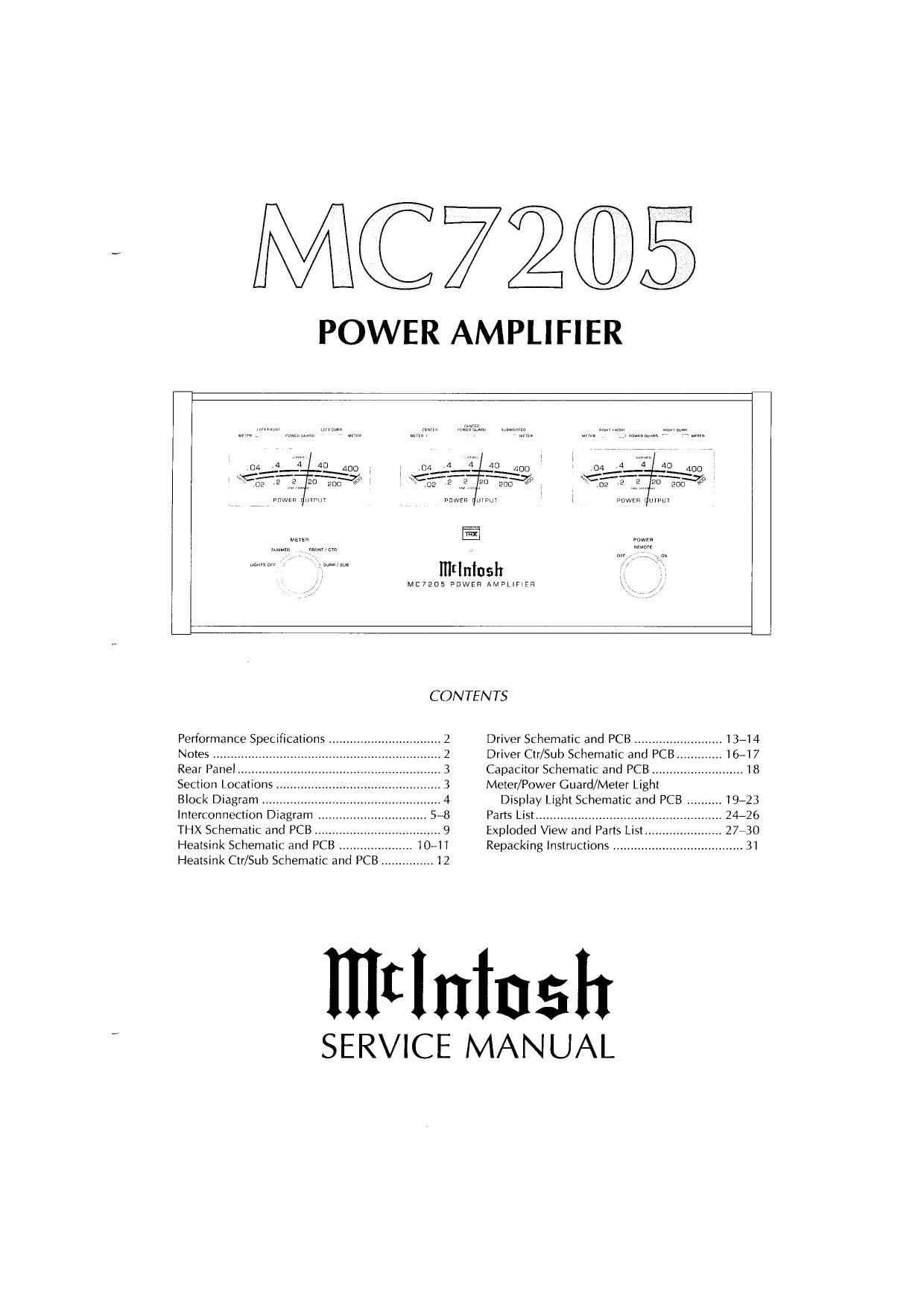
MC7205

POWER AMPLIFIER

mtlniush
/ Mc72D5 POWER AMPLiFiER

CONTENTS
Performance Specifications 2 Driver Schematic and PCB .........
Notes ..... 2 Driver Ctr/Sub Schematic and PC
Rear Pane! 3 Capacitor Schematic and PCB ..
Section Locations , 3 Meter/Power Guard/Meter Light
Block Diagram t. .4 Display Light Schematic and PCB ..........
Interconnection Diagram . 5-8 Parts Listm
THX Schematic and PCB .9 Exploded Vlew and Parts List.
Heatsink Schematic and PCB 10-11 Repacking Instructions

Heatsink Ctr/Sub Schematic and PCB ............... l2

IIItlninsh

SERVICE MANUAL

Page 2

PERFORMANCE SPECIFICATIONS

POWER OUTPUT PER CHANNEL
200 watts into 4 ohm loads or 120 watts into 8
ohm loads minimum sine wave continuous
average power output per channel, all channels
operating.

OUTPUT lOAD IMPEDANCE
8 or 4 ohms

RATED POWER BAND
20Hz to 20,000Hz

DYNAMIC HEADROOM
I .6dB

FREQUENCY RESPONSE
+0, 70.25dB from 20Hz to 20,000Hz
+0, -3dB from 10Hz to 100,000Hz

TOTAL HARMONIC DISTORTION
0.005% maximum at any power level from 250
milliwatt to rated power per channel from 20Hz
to 20,000Hz, all channels operating.

INTERMODULATION DISTORTION
0.005% maximum if instantaneous peak output
per channel does not exceed twice the rated out
put with all channels operating for any combina-
tion of frequencies from ZOhZ to 20,000hz.

SIGNAL TO NOISE RATIO
113dB below rated output, (A Weighted]

1. The heavy lines on the schematics denote the
primary signal path.

2. Unless otherwise noted, all voltages indicated on
the schematics are measured under the following
conditions:

3. AC input at 120 volts, 50/.60Hz.

b. All voltages are +/.10% with respect to ground.
A high impedance (10 megaohm) voltmeter
must be used.

3. Unless otherwise specified:

a. Resistor values are in ohms.
b. Capacitor values are in microfarads (uF).
c.1nductor values are in microheneries (UH)

SENSITIVITY
1 volt (2.0V at level control center delent position)

INPUT IMPEDANCE
10,000 ohms

DAMPING FACTOR (WIDE BAND)
200 @ 8 ohms
100 @ 4 ohms

POWER SUPPLY ENERGY STORAGE
215 Joules

POWER REQUIREMENTS

100 Volts, 50/60Hz at 1080 watts

110 Volts, 50/60Hz at 1080 walls

120 Volts, 50/60Hz at 1080 watts

120 Volts, 50/60Hz at 1080 watts

230 Volts, 50/60Hz at 1080 watts

240 Volts, 50/60H2 at 1080 watts

(Refer to rear panel of the MC7205 for the correct
voltage)

DIMENSIONS
Front Panel: 17-1/2 inches (44.5cm) wide, 7-1/16
inches (17.9cm) high. Depth behind front mount»
ing panel is 2l inches (53.3cm) including clear-
ance for connectors. Panel clearance required in
front of mounting panel is 1-1/8 inches (2.9cm)

WEIGHT
53 pounds (24kg) net, 72 pounds (32kg) in
shipping canon

NOTES

4. On PC board drawings, Square pads indicate:
a. Polarized Capacitors - Positive
b. Diode - Cathode
c. Others A Pin
5. WARNING:
Parts marked with the symbol have critical
characteristics. Use only replacement parts recom»
mended by the manufacturer.