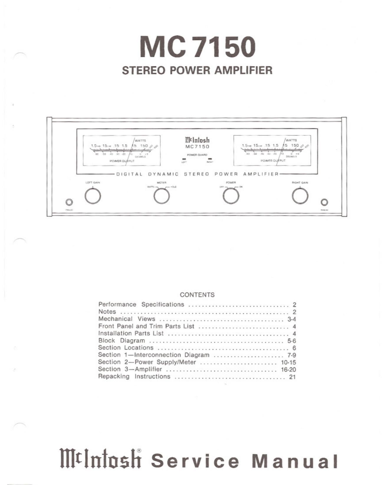
McIntosh MC 7150 Service Manual

This is the 22 pages manual for McIntosh MC 7150 Service Manual.
Read or download the pdf for free. If you want to contribute, please mail your pdfs to info@audioservicemanuals.com.

Page: 1 / 22
left right
McIntosh MC 7150 Service Manual

Extracted text from McIntosh MC 7150 Service Manual (Ocr-read)


Page 1

MC 7150

STEREO POWER AMPLIFIER

V -_ - j: j (Intush [. 7 .- 7 huvE «1

l 15-15. I5 15,45 50: MC7150 15-15,. 15 i5 5 ism-.1»

v! ! WM ##l
masnoqk; :- 3

L __ l ._ , l __

DIGITAL DYNAMIC SYEHEO POWER AMPLIFIER

.w m fl... m. ..»... w.
o O C5 C O 0
CONTENTS
Performance Specifications ............................. 2
Notes .................................................. 2
Mechanical Views ..................................... 34
Front Panel and Trim Parts List ........................... 4
Installation Parts List .................................... 4
Block Diagram ........................................ 5-6
Section Locations ........... V ........................... 6
Section 1-Interconnection Diagram ..................... 7-9
Section 2-Power Supply/Meter ....................... 10-15
Section 3-Amplilier ................................. 16-20
Repacking Instructions ................................. 21

mtlninsfi Service Manual

Page 2

Performance
Specifications

STEREO POWER OUTPUT

150 watts into 8, a or 2 ohm loads is
the minimum sine wave continuous average
power output per channel from 20Hz to
20.000Hz with both channels operating.
The output RMS voltage is:

3b.6 across 8 ohms

2A.!) across A ohms

17.3 across 2 ohms

OUTPUT LOAD IMPEDANCE
Stereo: 8, h or 2 ohms by connecting to
the proper output terminals.

RATED POWER BAND
20Hz to 20kHz

TOTAL HARMONIC DISTORTION

Stereo: 0.005% maximum harmonic
distortion at any power level from 250
milliwatts to rated power per channel from
20Hz to 20,000Hz. both channels operating.

INTERMODULATION DISTORTION

Stereo: 0.0051 maximum if instmtaneous
peak power output does not exceed twice
the output rating per channel, with both
channels operating. for any combination of
frequencies from 20Hz to 20,0mHz.

Notes

I. The heavy lines on the schematics
denote the primary signal path.

2. Unless otherwise specified:
a. Resistor values are in ohms.
b. Capacitor values smaller that 1 are
in mlcrofarads (uF) and greater than
1 are in picofarads (pF).
c. Inductor values are in microhenries
(uH).

3. Unless otherwise noted, all voltages
indicated 01 the schematics are
measured under the following conditions:
5. AC input at 120 volts, 50/60Hz.

b. All voltages are 210% with respect to
gromd.
A high impedance (10 megohm)
voltmeter must be used.

FREQUENCY RESPONSE (at one watt output)
+0, -0.Z§dB from 20Hz to 20,000Hz
+0, -J.0dB from 10Hz to 100,000Hz

HUM AND WISE (A-welghted)
110d8 below rated output

IHF DYNAMIC HEADROOM
1.868

DAMPING FACTOR
Greater than 40

INPUT IMPEDANCE
20. 000 ohm

INPUT SETSITIVITY
1.5 volts (2.5V at gain control center
detent)

POWER REQUIREMENT
120 volts, 50/60Hz, .5 to 7 amperes

c. Front panel controls are set at:
POWER......................ON
LEFT GAIN .......... FULLY CVI
RIGHT GAIN.... .....FULLY CW
METER SELECTOR. . . . . . . WATTS

b. The voltages enclosed in a box are
signal voltages that are measured with a
1.4V, IkHz signal connected to both
inputs.