McIntosh MC 60 Brochure

This is the 2 pages manual for McIntosh MC 60 Brochure.
Read or download the pdf for free. If you want to contribute, please mail your pdfs to info@audioservicemanuals.com.

Page: 1 / 2
left right
McIntosh MC 60 Brochure

Extracted text from McIntosh MC 60 Brochure (Ocr-read)


Page 1

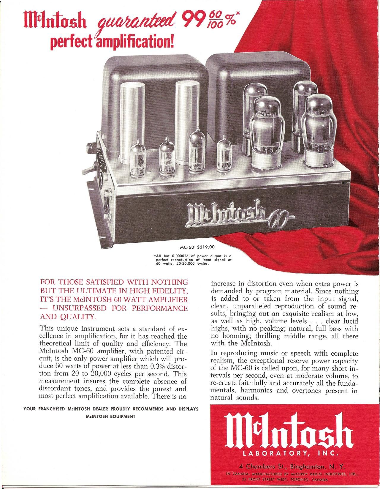
*All but 0.000015 of power amp.» is a
perfed reprodudiun of input Signal a!
so wufis, 20.2o,ooo cycles.

FOR THOSE SATISFIED WITH NO KING
BUT THE TIMI-STE 1N HiGH FIDELITY,
lTS THE McINTOSH 60 VVATT AMPLIFIER
- UNSURPASSED FOR PERFORMANCE
AND QUALETY.

This unique instrument sets a standard of ex-
cellence in amplification, for it has reached the
theoretical limit of quality and elficiency. The
McIntosh MC-60 amplifier, with patented cir-
cuit, is the only power amplifier which will pro-
duce 60 watts of power at less than 0.3% distor-
tion from 20 to 20,000 cycles per second. This
measurement insures the complete absence of
discordant tones, and provides the purest and
most perfect amplification available. There is no

YOUR FRANCHISED leNTOSH DEALER FROUDlY RECOMMENDS AND DISPLAYS

McINTOSH EQUIPMENT

MC-60 $219.00

increase in distortion even when extra power is
demanded by program material. Since nothing
is added to or taken from the input signal,
clean, unparalleled reproduction of sound re-
sults, bringing out an exquisite realism at low,
as well as high, volume levels . . _ clear lucid
highs, with no peaking; natural, full bass with
no booming; thrilling middle range, all there
with the McIntosh.

In reproducing music or speech with complete
realism, the exceptional reserve power capacity
of the MC-60 is called upon, for many short in-
tervals per second, even at moderate volume, to
re-create faithfully and accurately all the funda-
mentals, harmonics and overtones present in
natural sounds.

A F: '

4 Chambers St, Binghamton, N. Y.

IN CANADA: MANUFACTURED BY McCURDY lADIO INDUSTRIES, ITD.;
72 FRONT SYKEET WESY, TOIONIO. CANADA

Page 2

Power Supply:

Power Consumplinn:

Power Oulpul:

Inpul Level:

Frequency Range:

Harmonic Dislaflian:

lnlermodulalion

MC-éO SPECIFICATIONS

WW/

117/125 volls, 50/60 cycles

280 walls at 60 walls oulpul
155 walls at zero signal oulpul

60 walls conlinuous

Inpul #1 (pin jack and screw terminals)
,5 volls lo 30 volls, wilh gain conlrol
Input #2 2.5 volls

20 lo 30,000 cycles i 0.1 db al 60
walls oulpul
15 lo 50.000 cycles i
walls oulpul
l0 lo 100,000 cycles : i

walls outpul

0.5 db at 60

db at 30

Less than 0.37., al so wotls aulpul or
less, 20 to 20.000 cycles

less limit 05% if inslanloneous peak

Distortion: power is below 120 walls far any com-
bination of frequencies 20 to 20,000
cycles

lmpulse Dislarlion: Negligible

lav.

aw.

Noise and Hum Level: 90 db or more below ruled oulpul

15 or beller for 4, 8 and 16 ohm output,
16 for 600 ohms

Damping Faclor:

0.5 meg for 0.5 volt input and 0.13 meg

lnpul Impedance:
for 2.5 voll inpul 20 cycles in 40,000

4, 8, I6, 600 ohms (600 ohm is balanced

Oulpul Impedance:
lo ground), and 70.7 volls

Phase Shifl: i 8° 20 lo 20,000 cycles

Rectifier: 2.5u4 GA
Pre-Amp: 12AX7
Phase Inverter: 12AU7
Voltage Amp: I23H7
Driver: 12AX7
Oulpul: 2-6550/KTES

Tube Complemenl:

Auxiliary Equipmenl Designed lo power McIntosh Preamplifier:

Connoclian:

Sire: 14V. x 10 x a high, enessis lype m.
slruclion

Weighl: 42 pounds, 115 ounces

LOW DISTORTION MEASUREMENTS, guaranleed by thorough laboralory lesls on each unit shipped.

DISTORTION vs. POWER OUTPUT

PHASE SHIFT vs. FREQUENCY

,meuoxc

,- 204: ~ t 2 KC , l i
i VYFiCAl Mummers
~ - _ _ .,_ _ _

l r i

on 75
70W ourwl w ms wms

SINGLE FREQUENCY HARMONIC DISTORTiON

mu m s I K:
FfouEhCV w crass

GAIN-FREQUENCY CHARACTERISTlCS

7x: 5x: ioKC FDKI sex: 111ch

l i i i i i
i GUARANYEED MAX VAILlE AV an WAVIS l
-----4 ______ l.-- __,___ __ __
. i' l c .i. .0 ms .
i i r er s.
wrnrri MEASUIEMEvaaa wrm . l
i . i it rs. i i , .
in 2D 50 mo m sna i Kc 1 re 5 re to re in KL so r: «.aa rc in 70 sn we ran r K 7 K( s x( to L: in r: so Kc

rsmumcv iN CYClES

The famous Mclnlosh patenled Unily
Coupled circuit with hifllar oulpul
lransformer as used in all McIntosh
power amplifiers.

WI

The McIntosh circuit is fundamentally new. It provide practically
100% coupling between primary windings of the output transformer
by Winding the primary wires together, or bifilarly. For the first
time the high efficiency of class B amplification can be used with
high quality performance. Wave form distortion, causing listening
irritation, due to switching transients between each half of the
class, B amplifier is eliminated at all frequencies.

Before. 1947, truly faithful amplified sound was severely limited by:
(1), too much distortion; and (2) not enough power capacity. With
the invention of the McIntosh circuit for the first time less than 1%
distortion became the performance standard.

The McIntosh circuit has an inherent large advantage over conven-

5 ion r:
memo w Cvclrs

the exclusive Patentendlntosh Circuit
brings you purest High Fidelity Sound .. .

tional circuits. By bringing the output tubes electrically four times
closer together the impedance is 1A that of the conventional circuit.
The coupling to the secondary is improved by a similar factor of
4 to 1 since the primary to secondary turns ratio has been reduced
2 to 1. The 1/2 cathode, 1/2 plane loading provides a feedback factor
of 12 db, which with additional loop feedback, offers the lowest dis»
tortion, most stable power amplifier made.

To date, McIntosh amplifiers alone are able to provide less than
0.3% harmonic distortion and less than 0.5% intermodulation dis-
tortion (discordant distortion), for any frequency or for any combina-
tion of frequencies, throughout the audio range, even at full power
output. ,

*Mclntosh Laboratory, Inc, introduced Unity Coupling to High Fidelity in LL 5. Patents 2,477,074 (l949); also 2,545,788; 2,646,467; 2,654,058