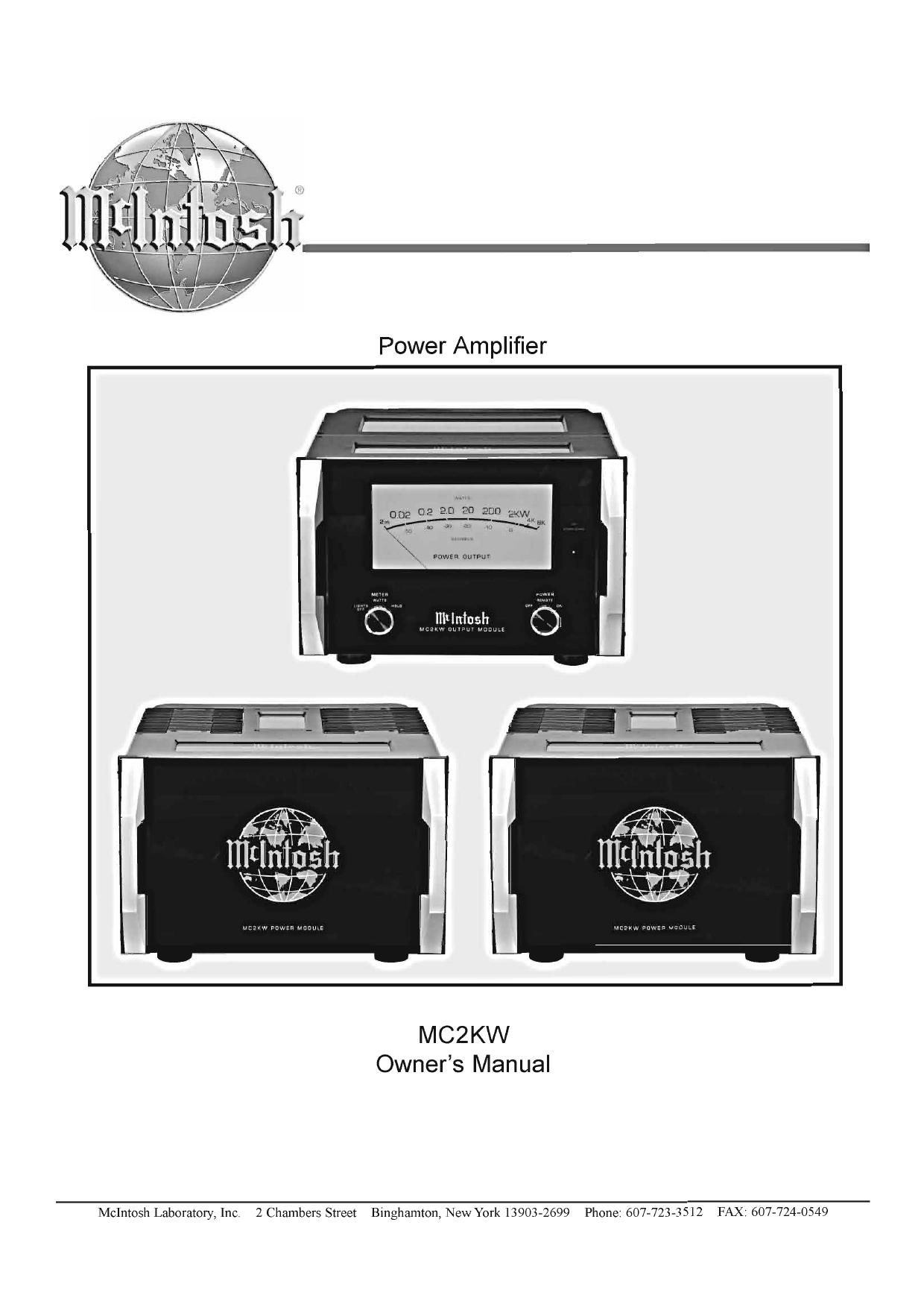
McIntosh MC 2KW Owners Manual

This is the 32 pages manual for McIntosh MC 2KW Owners Manual.
Read or download the pdf for free. If you want to contribute, please mail your pdfs to info@audioservicemanuals.com.

Page: 1 / 32
left right
McIntosh MC 2KW Owners Manual

Extracted text from McIntosh MC 2KW Owners Manual (Ocr-read)


Page 2

The lightning flash with arrowhead,
within an equilateral triangle, is in-
tended to alert the user to the presence

of

within the products enclosure that may

be

a risk of electric shock to persons.

uninsulated dangerous voltage

of sufficient magnitude to constitute

WARNING - TO REDUCE RISK OF
FIRE OR ELECTRICAL SHOCK, DO
NOT EXPOSE THIS EQUIPMENT TO

RAIN OR MOISTURE.

AVIS RISQUE DE 01400 ELECTRIGUE-NE PAS ouvnm.

The exclamation point within an

equilateral triangle is intended to
CAUTION alert the user to the presence of im-
RISKogthgggggfiHOCK portant operating and maintenance

(servicing) instructions in the litera-
ture accompanying the appliance.

NO USER-SERVICEABLE PARTS
INSIDE. REFER SERVICING TO
QUALIFIED PERSONNEL.

To prevent the risk of electric shock, do not remove cover or
back. No user-serviceable parts inside.

1
2
3
4
5
6
7

8

9

10.

11.

12.

IMPORTANT SAFETY
INSTRUCTIONS!

PLEASE READ THEM BEFORE
OPERATING THIS EQUIPMENT.

. Read these instructions.

. Keep these instructions.

. Heed all warnings.

. Follow all instructions.

. Do not use this apparatus near water.

. Clean only with a dry cloth.

. Do not block any ventilation openings. Install in
accordance with the manufacturers instructions.

. Do not install near any heat sources such as
radiators, heat registers, stoves, or other apparatus
(including amplifiers) that produce heat.

. Do not defeat the safety purpose of the polarized

or grounding-type plug. A polarized plug has two

blades with one wider than the other. A grounding
type plug has two blades and a third grounding
prong. The wide blade or the third prong are
provided for your safety. If the provided plug does
not fit into your outlet, consult an electrician for
replacement of the obsolete outlet.

Protect the power cord from being walked on or
pinched particularly at plugs, convenience

receptacles, and the point where they exit from

the apparatus.

Only use attachments/accessories specified by the

manufacturer.

Use only with the cart, stand, tripod, bracket, or
table specified by the manufacturer, or sold with

the apparatus. When a cart is used,
use caution when moving the cart/
apparatus combination to avoid
injury from tip-over.

13. Unplug this apparatus during
lightning storms or when unused for long periods
of time.

14. Refer all servicing to qualified service personnel.
Servicing is required when the apparatus has been
damaged in any way, such as power-supply cord
or plug is damaged, liquid has been spilled or
objects have fallen into the apparatus, the
apparatus has been exposed to rain or moisture,
does not operate normally, or has been dropped.

15. Do not expose this equipment to dripping or
splashing and ensure that no objects filled with
liquids, such as vases, are placed on the
equipment.

16. To completely disconnect this equipment from the
ac. mains, disconnect the power supply cord plug
from the ac. receptacle.

17. The mains plug of the power supply cord shall
remain readily operable.

18. This apparatus is capable of driving
Loudspeakers (even low efficiency tvnes) into

producing extremely high sound pressure
levels. Use; caution is advised. Ear protectiop
is recommended when playing at high volumes
as continued exposure to high sound pressure

levels can cause permanent hearing impair-
ment or loss.

19. Do not place the protective blue cloth cover on
the equipment when the power supply cord is
connected.

#

Page 13

How to Connect the MCZKW for Power Control and Audio
-

How to Connect the MCZKW for Power
Control and Audio connections

These two pages contain information for connecting to-
gether the McIntosh MC2KW Output Module and the
MC2KW Power Modules; and that combination to the
C1000 Preamplifier. McIntosh Power Control connections
allow for unified audio system operations; one push-button
press to switch the entire system On or Off.

The connection instructions below, together with the In-
put and Output Connection Diagrams located on the sepa-
rate folded sheet Mc2A, are an example of a typical au-
dio system. The following steps also include connections
from the McIntosh Preamplifier Right Channel Main Audio
Output to the MC2KW Power Amplifier (Right Channel).
The second MC2KW Power Amplifier (Left Channel) Au-
dio is connected in a similar manner.

Your system may vary from this, however the actual
components would be connected in a similar manner. For
additional information refer to Connector and Cable Infor-
mation on page 4.

1. Connect one of the supplied custom 16 Conductor
Cables from the MC2KW Output Module TO POWER
MODULE (A) Connector 1 to the MC2KW Power
Module (A) Connector 1.

Note: After the cable connector is firmly seated into the
chassis socket, rotate the locking collar clockwise
until it is tight (do not over tighten).

2. In a similar manner, connect the supplied custom 21
Conductor Cable from the MC2KW Output Module TO
POWER MODULE (A) Connector 2 to the MC2KW
Power Module (A) Connector 2.

3. Connect the remaining custom 16 Conductor Cable
from the MC2KW Output Module TO POWER MOD-
ULE (B) Connector 1 to the MC2KW Power Module
(B) Connector 1.

4. In a similar manner, connect the remaining custom 21
Conductor Cable from the MC2KW Output Module TO
POWER MODULE (B) Connector 2 to the MC2KW
Power Module (B) Connector 2.

5. Connect a Power Control Cable from the C1000C
Power Control Main Jack to the POWER CONTROL
IN Jack on the McIntosh MC2KW Output Module
(Right Channel). Then connect another Power Control
Cable from the McIntosh MC2KW Output Module
(Right Channel) POWER CONTROL OUT Jack to the
McIntosh MC2KW OUTPUT MODULE (Lefi Chan-
nel) POWER CONTROL IN In Jack.

Note: There is approximately a one-half second delay
added to the Power Control OutputJack voltage in
McIntosh PowerAmplyiers to reduce the strain on
the AC Power Line. This will delay the Turn-On of
the second McIntosh PowerAmplifier {left channel

in this system). If there are additional McIntosh
PowerAmplifiers in the system, connect the
POWER CONTROL OUTJack ofthe MC2KW
OUTPUTMODULE (Left Channel) to the Power
Control In on the next PowerAmpli er

6. Connect a XLR Cable from the C1000 Preamplifier or
Tube Preamplifier Main Right Output Balanced, to one
of the Balanced Inputs on MC2KW Output Module
(Right Channel).

Note: Unbalanced Inputs and Outputs may optionally be
used

7. Place the INPUT MODE Switch on the Rear Panel of
the MC2KW Output Module to the BALanced position
if Balanced Connections were utilized in step 6. If Un-
balanced Connections are used place the switch in the
UNBALanced position.

8. In a similar manner, connect a XLR Cable from the
C1000 Preamplifier or Tube Preamplifier Main Lefi
Output Balanced, to one of the Balanced Inputs on the
MC2KW Output Module (Left Channel).

Note: If both C1000P and C1000T Preamplifiers are
used in the system, the C1000 Tube Preampli er
Main Right Output Balanced connects to the
remaining Balanced Input on MCZK W Output
Module; the Lefi Channel is connected in a similar
manner.

9. Proceed to page 14 for the connection of Loudspeaker(s)
to the MC2KW Power Amplifier.

13