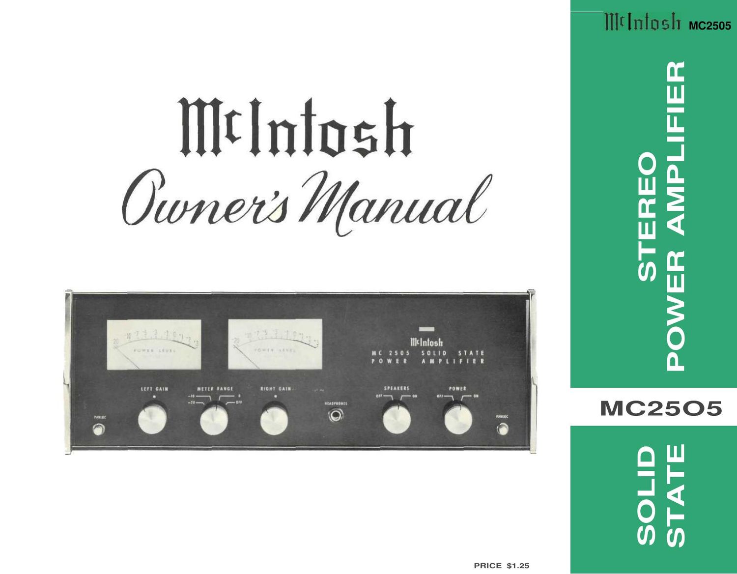
McIntosh MC 2505 Owners Manual

This is the 20 pages manual for McIntosh MC 2505 Owners Manual.
Read or download the pdf for free. If you want to contribute, please mail your pdfs to info@audioservicemanuals.com.

Page: 1 / 20
left right
McIntosh MC 2505 Owners Manual

Extracted text from McIntosh MC 2505 Owners Manual (Ocr-read)


Page 1

Page 2

The Mclntosh "will to perfection" requires that we probe constantly into the unknown to bring the performance of our electronic equipment closer to perfection than ever before. This requires a constant and relentless search for low noise, broad band conservative design with an ever lower distortion factor. This is not required of ordinary equipment of average designs. It is, for us, a costly but worthwhile scientific and engineering effort. Our continuing research benefits our cus- tomers with the almost complete lack of obsolescence and the most reliable equipment ever made. It also means the lowest long-range cost to you. Nearly all of the Mclntosh equipment ever made is still useable, or in use, though it may have been made twenty years ago. GENERAL DESCRIPTION 2 TECHNICAL DESCRIPTION 2,3 LOCKING METERS 4 PERFORMANCE CHARTS 5,6 CHARTS 8 SPECIFICATIONS 9 IN A HURRY 10 INSTALLATION 11 TYPICAL HOOKUP 12 CONNECTING 13 BLOCK DIAGRAM 14 OPERATING 15 GUARANTEE 16 MC2505 Your purchase of a Mclntosh instrument shows that you are a careful discriminat- ing buyer. One who is interested in quality performance, quality engineering, quality manufacturing, and long trouble-free equipment life. You can protect your in- vestment by spending a few minutes read- ing this owner's manual. When you bought a Mclntosh, you bought countless hours of musical pleasure and superior performance. Enjoy it! MC25O5 1 CONTENTS STEREO POWER AMPLIFIER SOLID STATE

Page 4

The output stages are matched to the load by the Mclntosh auto- former. The Mclntosh autoformer is carefully wound using Mcln- tosh trifilar winding and interleaving techniques. Trifilar winding and interleaving gives the transformers exceptional bandwidth. The autoformers properly match the power transistors to 4, 8, and 16 ohm loads at all audio frequencies. The use of the Mclntosh designed trifilar autoformer makes the Mclntosh solid state amplifiers the only amplifiers that deliver FULL POWER AT ALL SPEAKER IMPEDANCES. You have not been power penalized for your choice of loudspeakers when using the Mclntosh MC2505. Another of the advantages of the autoformers is the 25 volt output for a constant voltage distribution system. With the MC2505 sev- eral sets of speakers can be operated independently throughout your home. To further insure reliability a special power output SENTRY MONI- TORING CIRCUIT prevents failure of the power output transistors due to excessive mismatch of the output. When your MC2505 operates normally the SENTRY MONITORING CIRCUIT has no effect on signals passing through the power amplifier. If the power dissipation should rise above normal operation, the SEN- TRY MONITORING CIRCUIT restricts the drive to the output transistors. The SENTRY MONITORING CIRCUIT acts instantane- ously for any input signal or load combination. This arrangement assures complete circuit reliability. Only Mclntosh gives you this degree of protection. POWER SUPPLY SECTION There are three separate power supply sections. One positive and one negative high current supply is used for the output stages. The other positive supply is used for the driving amplifier stages. All supplies are full wave and use silicon rectifiers. Adequate filter- ing is used to assure an absolute minimum of hum. The power out- put stage filter capacitors have very high capacity, which allows full power output below 20 Hz. The power transformer is generous in size and runs cool, even under heavy use. 3

Page 5

Ordinary meters lack the capability of indicating the short interval power in a sound wave. The mass of the meter movement is too great to re- spond to instantaneous changes in music pro- gram material. Mclntosh superior engineering has developed new circuitry that permits the meters on the MC2505 to respond to the short interval power in a sound wave to an accuracy of 98% of the true value. This is another Mclntosh development that represents a major step for- ward in the use of power level meters. There are two circuits that give these meters the indicating capability of the short interval power in a sound wave. The first circuit is an accelerating circuit that compensates for the inertia characteristics of the meter movement. Because the short interval power fluctuation is so rapid, the eye might not perceive the instan- taneous power reading. This caused the devel- opment of the second circuit, which is a "time stretching" circuit. The time stretching circuit delays the movement of the meter needle at peak reading for a few milliseconds. With the aid of the CBS test record STR100, the frequency response of your phono cartridge can be measured. The graph on page 5 shows the ideal RIAA curve using the CBS record STR100. Follow these steps to plot the performance of your phonograph cartridge. 1. Set the "METER RANGE SWITCH" to the -20 position. 2. Play the 1000 Hz test tone recorded on the CBS Test Record STR100 on your phonograph. 3. Turn the "LEFT GAIN" control until the left meter indicates "0." 4. Turn the "RIGHT GAIN" control until the right meter indicates "O." 5. Write down the meter indication at each frequency as the record plays. 6. Transfer the readings by frequency to the graph. 7. The graph shows the ideal RIAA re- sponse curve using the CBS #STR100 test record. Compare your curve with the curve on the graph. A deviation of 3 dB from the ideal is acceptable. By making this check at regular intervals, (for instance, every 6 months) any deterioration in the cartridge or system will be quickly detected. DYNAMIC PEAK LOCKING METERS A tape recorder can be checked in the same fashion. 1. Use a standard frequency response tape as the signal source. 2. Complete all steps outlined for phono cartridges. 3. You now have a graph of the playback characteristics of your tape recorder. To find the record characteristics of the tape recorder follow this procedure: 1. Record the CBS Test Record #STR100 on your tape recorder. Adjust the record volume only on the 1000 Hz signal for proper recording level. DO NOT ADJUST THE RECORD VOLUME CONTROL DUR- ING THE RECORDING. 2. Play back the tape just recorded. Com- plete all steps outlined for tape playback characteristics. 3. A comparison of the two curves will give the recording characteristics of your tape recorder. A deviation of 3 dB is acceptable. Similar checks can be made on all program sources in your stereo system. Follow the same general procedure for any program source for which a standard reference is available. -1