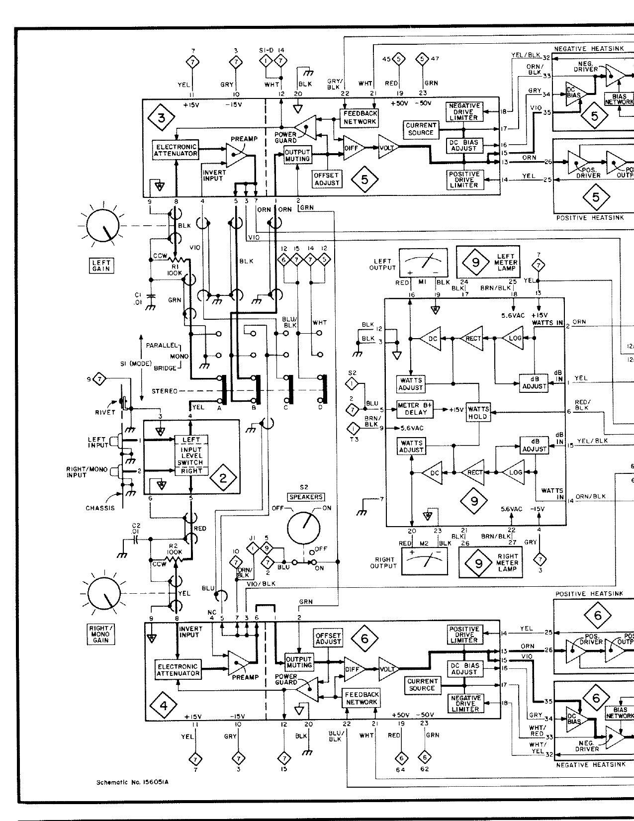
McIntosh MC 2255 Service Manual

This is the 32 pages manual for McIntosh MC 2255 Service Manual.
Read or download the pdf for free. If you want to contribute, please mail your pdfs to info@audioservicemanuals.com.

Page: 1 / 32
left right
McIntosh MC 2255 Service Manual

Extracted text from McIntosh MC 2255 Service Manual (Ocr-read)


Page 1

3 51-0 W NEGATIVE HEATSINK
BLK


7
NEG.
DRIVER
YEL any war ELK Sn
H 10 I2 20 22 2| I9
_ I
+I5v new I ¢ } +sov -5ov NSSAJIEVE
FEEDBACK I
I LIMITER 5
I-~-[- "Um cunnsm 1 .7
R E
FREAMF I 281% 5° c I
ELECTRONIC (£35,115 15
ATTENUATOR I 0079!. ,5
l uumx; 1" 0R" 6
T
|NVERT |
""UT 075" POST'VE YEL omovER oum
. DRIVE -I4_--25,_.-.-
% I I : ADJUSY LIMITER
\ I / s a a 5 3 7 | 2 ®
can
\ / L__fl() orm ORN L___
_ ... _ _ __ _ ELK () POS|TIVE HEATSINK
/ / \ ) wo
V'0 I2 I5 l4 l2
cow. 7
- m LE /7K flag?
IOOK OUTPUT + - LAMP
RED' MI 1am 24 25 YEL
BLKI gnu/am
21:: can I6 I9 I7 IS I3
@ 5.sVAc +I5v
ELK I2 WATTS m 2 can
BLK
PARALLEL] 3 m
mono W
1
SI (IncommeJ 2
52 as
WATTS as IN YEL
__ __ ADJUST Awusr""' ""' _
2
31.1: RED/
c D 5+MEJEEEA$+ +I5v WAYYS s ELK
BRN/ HOLD

@fls -u5,stc -

I: as ~-
wants as IN 5 YEL/ELK
ADJW ADJUST

mam/mono 2 6
INPUT _
E 52 WATTS e
s SPEAKERS 7 m ems/aw
I4
CHASSIS ocr-\ /-ON 5.6VAC ~I5v
02 6 T f
,on 23 an 22 a
K BLKI BRN/BLKI
[J7 RED M2 BLK 25 27 cm
R RIGHT
CC" OUITGPNUTT /7K METER
\ I / LAMP 3
\ /
- - POSITIVE HEATSINK
/ \
/ \
9
msnr/ INVERT l p
I I osmvE YEL
$37,? $ INPUT - | OFFSET DRIVE ~4
ADJUSY LIMITER
| L 3 can
I ouwur .5 we
ELECTRONIC I "WING DC BIAS ,5
AT
YEN 0 PREAMP POWER ADJUST
I Gum.) CURRENT I,
FEEDBACK SOURCE I
I fl m
+l5V -|5V l I f +sov -5ov
II Io I2 20 22 :1 IS 23
YEL GRY BLK at? WNT RED eim
NEG.
<7) 2_____.-'-
7 3 IS 54 62 NEGATIVE HEATSINK

Schtmafilc N0. I5605IA

Page 4

ARTS LIST

11111301 Part

Na. No. Description

PACITORS (CD : Ceram1c DISC. ELECT = Electrolytic.

MPE = Metalrzed Polyestert

C1 061159 CD. 0111?, +80 720%.501/
02 061159 00, 011%, +80 1» 20%. 50V
03 066331 ELECT. 38.000uF. 60V
04 066331 ELECT. 38.000179 60V
05 064267 MPE. 2214f 400V

WES (0010 : Br1dge. RECT : Rectmer.
81: 81110011)
'01 070092 St. BR1D. RECT. 354. 200V.
MDA3502

iHTING DEVICES (lNC :1ncandescent)
081 058014 WC. 6 3V. 25A. 1866
08? 058014 WC. 6 3V. 25A. 1866
083 058014 11110.6 3V. 25A. 1866
084 058014 11110.6 3V. 25A. 1866

SES and FUSEHDLDERS (FA -~ Fast AC11011)

F1 174188 Fus1b1e Link. #30 solid copper w1re
F2 089042 FA. Fuse 15A. 250V. A8015
178114 Fusehomer. UL/CSA~S101.
Bussman HMM

ETERS
'M1 124034 Meter
M2 124034 Meter

SISTORS (CF: Carbon Fatm, MF : Metal F111111

'111 134273 L61IGa111 00111101

'RZ 134273 Right/Mono 6am 00111101
113 144148 MF.3161<12.1%.1/4w
'84 144113 MF.1001<12 1%.1/4W
'11?) 144148 MF 3161(1). 1% 174W
'RS 144113 MF.100k12.1%.1/4W
117 141057 CF. 2 21(1) 5%.1/4W

ERMISTORS
'RT1 144151 Thermlstor. 512
RTZ 144151 11191111151111.517

IITCHES
'81 148055 Mode Swrtch
82 145183 Speake1Swilcn
83 146214 Meter Range Swrtch
'34 148052 Tone Swan
85 148052 Speed Swrtch
'86 146183 Power Swrtch
'87 153017 Thermat CutaOut Sw1tch
88 153017 11151111311 Cut-Out Swrtch

ANSFORMERS
'T1 045721 A0010
12 045721 Audio
"'13 045722 Power

SCELLANEOUS
084038 8113111 Relre1 (Lme Cord)
117009 AC Receptame Black
J1 117049 Headphone Jack 3/8
170133 Lme Cord. 16 Ga

1511121111611 w11har1asterrsl< ['1 are restatement parts stock'
1y our Servme Department and must be ordered 110111
11110511 These 0811511108108 ordered by part 110111681 Parts
narked may be untamed 110m etectromc parts 51191311515

31
@103 01

NOTES

14.

1 72.

13.

It the power transformer is suspected of a
malfunction. the DC resistance of the wind-
ings must be checked before replacement.
The measurements are made mm the
primary wrndrngs drsconnected, Actual DC
reSIstance measurements can vary by
120%.

SEN to WHT/BRN .0461)
RED to RED/YEL .0331!
WHT/BLK 10 YEL/BLK .05611
YELIBLK 10 BLK 0.2511

GRNIBLK 10 ORN/BLK .0561)
ORN/BLK to RED/ELK 0.2511

When replacrng bridge rectifier D1 make sure
to apply a1ayer of heatsink compound (Dow
Cornlng 340 or equivalent) to the metal bot-
tom 01 the rectltrer betore installrng on the
heatsink.

H the au1otrans1ormer is suspected of a
malfunction. the DC resnstance of the windv
rngs must be checked betore replacement.
The measurements are made With all wind-
mgs disconnected, Actuat DC resistance
measurements can vary by z 20%.

ORN to GRN 0.240
GEN 10 RED 0,1012
RED to BLU 0,1312
BLU to WHT 0,360
BLU to BLK 0,241?

WARNING! F1lter capac1tors C3 and 04 have
high energy storage capacrly Before servrc
mg, disconnect amphher 110m AC line
voltage and discharge bolh capacitors to
chassis ground through a resrstor