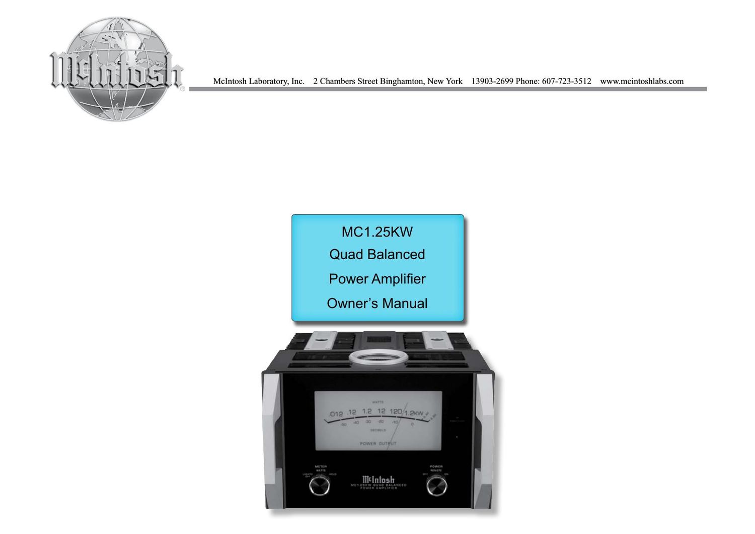
McIntosh MC 1.25KW Owners Manual

This is the 20 pages manual for McIntosh MC 1.25KW Owners Manual.
Read or download the pdf for free. If you want to contribute, please mail your pdfs to info@audioservicemanuals.com.

Page: 1 / 20
left right
McIntosh MC 1.25KW Owners Manual

Extracted text from McIntosh MC 1.25KW Owners Manual (Ocr-read)


Page 1

2 Your decision to own this McIntosh MC1.25KW Quad Balanced Power Amplifier ranks you at the very top among discriminating music listeners. You now have The Best. The McIntosh dedication to Quality, is assurance that you will receive many years of musical enjoyment from this unit. Please take a short time to read the information in this manual. We want you to be as familiar as pos- sible with all the features and functions of your new McIntosh.Copyright 2017 © by McIntosh Laboratory, Inc. Table of Contents Thank You Please Take A Moment Technical Assistance If at any time you have questions about your McIntosh product, contact your McIntosh Dealer who is familiar with your McIntosh equipment and any other brands that may be part of your system. If you or your Dealer wish additional help concerning a suspected problem, you can receive technical assistance for all McIntosh products at: McIntosh Laboratory, Inc. 2 Chambers Street Binghamton, New York 13903 Phone: 607-723-3512 Fa x: 607-724 - 0549 Customer Ser vice If it is determined that your McIntosh product is in need of repair, you can return it to your Dealer. You can also return it to the McIntosh Laboratory Service Department. For assistance on factory repair return procedure, contact the McIntosh Service Department at: McIntosh Laboratory, Inc. 2 Chambers Street Binghamton, New York 13903 Phone: 607-723-3515 Fa x: 607-723 -1917 The serial number, purchase date and McIntosh Dealer name are important to you for possible insurance claim or future service. The spaces below have been provided for you to record that information: Serial Number: Purchase Date: Dealer Name: Important Safety Information is supplied in a separate document Impo\ rtant Additional Operation Information Guide Safety Instructions .............................................................. 2 (Separate Sheet) ............................Important Additional Operation Information Guide Thank You and Please Take a Moment ............................... 2 Technical Assistance and Customer Service ....................... 2 Table of Contents ................................................................. 2 General Information ............................................................ 3 Connector and Cable Information .............................. 3 Introduction ................................................................. 4 Performance Features ................................................. 4 Dimensions ................................................................. 5Installation .................................................................. 6 Rear Panel Connections and Switch ........................... 7 Output Terminals and How to Connect .................. 8-9 Output Terminals and How to Connect for Bi-Amp ......................................................... 10-11 Front Panel Displays and Controls ............................ 12 How to Operate ......................................................... 13 Technical Description .......................................... 14-17 Specifications ............................................................ 18 Packing Instruction ................................................... 19

Page 2

3 XLR Connectors Below is the Pin configuration for the XLR Balanced Input, Input/Output Connectors on the MC1.25KW. Refer to the diagram for connection: PIN 1: Shield/Ground PIN 2: + Input/Output PIN 3: - Input/Output Power Control Connector The MC1.25KW Power Control Input (Trigger Con- trol) receives an On/Off signal from +5 to +12 volts. The Power Control Output will in turn provide a +12 volt Output Signal with a total cur- rent up to 50mA. An additional connection is for controlling the illumination of the McIntosh Power Output Meters. The 3.5mm stereo mini phone plug connects to another McIntosh Power Amplifier. Output Terminal Connector When cables with spade lugs are used for Loudspeaker Connection, the spade lugs need an opening of at least 3/10 inch (7.6mm) 5. The MC1.25KW incorporates the very latest in Fully Double Balanced Circuitry. As a result, the Loudspeaker Negative Connections are above chassis ground. Do not combine any connections together, ground them or connect with another MC1.25KW. 6 . In the event the MC1.25KW over heats, due to im- proper ventilation and/or high ambient temperature, the protection circuits will activate. The Front Panel Power Guard LED will continuously indicate ON and the audio will be muted. When the MC1.25KW has returned to a safe operating temperature, nor- mal operation will resume. 7. When discarding the unit, comply with local rules or regulations. Batteries should never be thrown away or incinerated but disposed of in accordance with the local regulations concerning battery disposal. 8. For additional information on the MC1.25KW and other McIntosh Products please visit the McIntosh Web Site at www.mcintoshlabs.com. Caution: The MC1.25KW Amplifier weight is 158 pounds (71.7 kilograms). It requires two or more per- sons to safely handle when moving the ampli- fier. 1. For additional connection information, refer to the owners manual(s) for any component(s) connected to the MC1.25KW. 2. The MC1.25KW mutes the speaker output for ap- proximately two seconds when first turned on. 3. For the best performance and safety it is important to always match the impedance of the Loudspeaker to the Power Amplifier connections. Refer to How to Connect pages 8 thru 11. Note: The impedance of a Loudspeaker actually var ies as the Loudspeaker reproduces different frequencies. As a result, the nominal impedance rating of the Loudspeaker (usually measured at a midrange frequency) might not always agree with the impedance of the Loudspeaker at low frequencies where the greatest amount of power is required. Contact the Loudspeaker Manufac turer for additional information about the actual impedance of the Loudspeaker before connecting it to the McIntosh MC1.25KW. 4. It is very important that loudspeaker cables of ad-equate size be used, so that there will be no power loss. The size is specified in Gauge Numbers or AWG, (American Wire Gauge). The smaller the Gauge number, the larger the wire size: If your loudspeaker cables are 50 feet (38.1m) or less, use at least 14 Gauge. If your loudspeaker cables are 100 feet (76.2m) or less, use at least 12 Gauge. General Information Connector and Cable Information Trigger Control Ground Meter Illumination Control PIN 1 PIN 2 PIN 3 PIN 2 PIN 1 PIN 3 OUT IN 3/10 of an inch (7.6millimeters) General Information and Cable Information