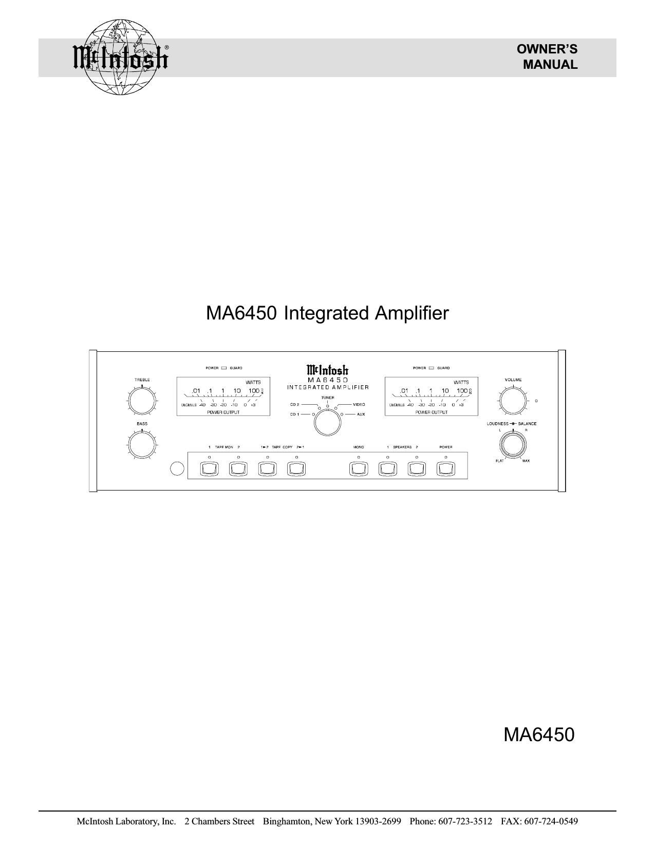
McIntosh MA 6450 Owners Manual

This is the 16 pages manual for McIntosh MA 6450 Owners Manual.
Read or download the pdf for free. If you want to contribute, please mail your pdfs to info@audioservicemanuals.com.

Page: 1 / 16
left right
McIntosh MA 6450 Owners Manual

Extracted text from McIntosh MA 6450 Owners Manual (Ocr-read)


Page 2

Thank You

For your decision to own this Mclntosh MA6450 Inte-
grated Amplifier ranks you at the very top among discrimi-
nating music listeners. You now have The Best. The
Mclntosh dedication to Quality, is assurance that you
will receive many years of musical enjoyment from this
unit.

Please take a short time to read the information in this
manual. We want you to be as familiar as possible with all
the features and filnctions of your new Mclntosh MA6450.
This will ensure that you receive all the performance ben-
efits this equipment can offer you, and that it will become a
highly valued part of your home entertainment system.

Please Take A Moment

The serial number, purchase date and McIntosh dealer name
are important to you for possible insurance claim or future
service. The serial number is located on the rear panel of the
equipment. The spaces below have been provided for you to
record that information:

Serial Number:

Purchase Date:

Dealer Name:

Customer Service

If at any time you have questions about your Mclntosh
MA6450 Intergrated Amplifier, contact your Mclntosh
dealer Your dealer is familiar with your Mclntosh equip-
ment as well as other brands that may be included in your
system and is best qualified to help you.

If it is determined that your MA6450 is in need of repair,
you can return it to your dealer or you can retum it to
Mclntosh Laboratory. Contact the Mclntosh Repair Depart-
ment for assistance at,

Mclntosh Laboratory, Inc.

2 Chambers Street
Binghamton, New York 13903
Phone: 607-723-3512

FAX: 607-724-0549

Copyright 1997 © by Mclntosh Laboratory, Inc.

Thank You, Please Take A Moment,
Customer Service and Table of Contents

Table of Contents
Thank You .........................
Please Take a Moment
Customer Service ..
Table of Contents ..
Safety Instructions
Introduction .................
Performance Features .
Installation ........................
Rear Panel Connections
How to Connect ......................................
How to Connect for Video Switching .....
Front Panel Controls, Displays, Push-Buttons,

and Switches ...................................................................... 9


How to Operate .................... 10
HR-033 Push-Buttons iiiiii 12
How to Operate by Remote Control ...... 13
Specifications ............................................ 14
Packing Instruction .......................................................... 15
NOTES:
1. Connecting Cables are available fiom the Mclntosh Parts
Department:

Data and Power Control Cable Part No. 1 70-202
Six foot, shielded 2 conductor, with 1/8 inch stereo mini
phone plugs on each end.

2. For additional connection information, refer to the owner s
manualfls) for any c0mponent(s) connected to the [VI/16450
Ampli zer.

3. There is a built-in turn on delay which will mute the speaker
outputs for approximately two seconds when the ampli ier is
turned on.

4. 1f the rear panel processor switch is set to the in position, and
a signal processor is not connected, no sound will be heard
through the system. When a signal processor is connected to
the MA645 0 processor jacks, and the processor switch is set
to the in position, the processor must be on and operating, or
in bypass mode, for a sound to be heard through the system.

5. It is very important that loudspeaker cables of adequate size
be used in your music system, to ensure that there will be no
power loss or heating. Cable size is specified in Gauge
numbers orAWG, (American Wire Gauge). The smaller the
Gauge number, the larger the wire size:

If your loudspeaker cables are 25 feet (7. 62m) or less,
use at least 18 Gauge (A WG) wire size or larger.

If your loudspeaker cables are 5 0 feet (38.1m) or less,
use at least 16 Gauge (A WG) wire size or larger.

If your loudspeaker cables are 100feet (76.2m) or less,
use at least 14 Gauge (A W G) wire size or larger.

Page 7

How to Connect the MA6450

1. Connect the MA6450 power cord to a live AC outlet.

2. Connect cables from a pair of speakers to the
SPEAKER l Outputs.

Note: After connecting the
loudspeakers, install the
supplied protective covers
(located in an accessory
package in the shipping
carton) over the loudspeaker
terminals.

3. Connect a cable from the TAPE 1 OUTPUTS to the
Record Inputs of a tape recorder and the TAPE 1 IN-
PUTS to a tape recorder Outputs.

4. Connect cables from a McIntosh CD Player to the CD1
INPUTS. Connect a McIntosh tuner to the TUNER IN-
PUTS.

5. Connect a cable from the POWER CONTROL jack to

How to Connect the MA6450

the Power Control In on a McIntosh component or
Power Controller.

6. Connect a cable(s) from the DATA PORTS to the com-
ponents that are to be controlled by the MA6450.

7. Connect a Coax cable from the EXT SENSOR to a
McIntosh wall sensor or WK-2 Keypad in a second
room.

NOTE: [fa Signal Processor is Used, connect cables from the
Signal Processor Outputs to the PROCESSOR FROM
jacks and the Signal Processor Inputs to the
PROCESSOR TOjacks. Set the MA6450 PROCESSOR
switch to IN. The processor must he on or in bypass
mode for a signal to be heard.

McIntosh CD Player

Tape Recorder

" -|] DE

2 m

:ll

pp .

{a V. o a

Signal Processor

o-IIotmobooowo W

I-

(<3

7,. W" % "MW WDWJSTTI flawwi fl was , W
m I I ,Ng$gxgggaegn mm M
wmmw ] a Mama) .
Q2) (El \.
Io V CI
I ,I
To AC Outlet I' - - - I
I a I
| I |
| e |
// / l / McIntosh I *
é? é? ' é? é? 35333? '
// rr I z/ pr
|

Right Loudspeaker Left Loudspeaker

I
L Egawweeecwyugsvgkg _ _ _ 4 Wm P03