McIntosh GT 320 GT 340 GT 360 GT 112 Owners Manual

This is the 2 pages manual for McIntosh GT 320 GT 340 GT 360 GT 112 Owners Manual.
Read or download the pdf for free. If you want to contribute, please mail your pdfs to info@audioservicemanuals.com.

Page: 1 / 2
left right
McIntosh GT 320 GT 340 GT 360 GT 112 Owners Manual

Extracted text from McIntosh GT 320 GT 340 GT 360 GT 112 Owners Manual (Ocr-read)


Page 1

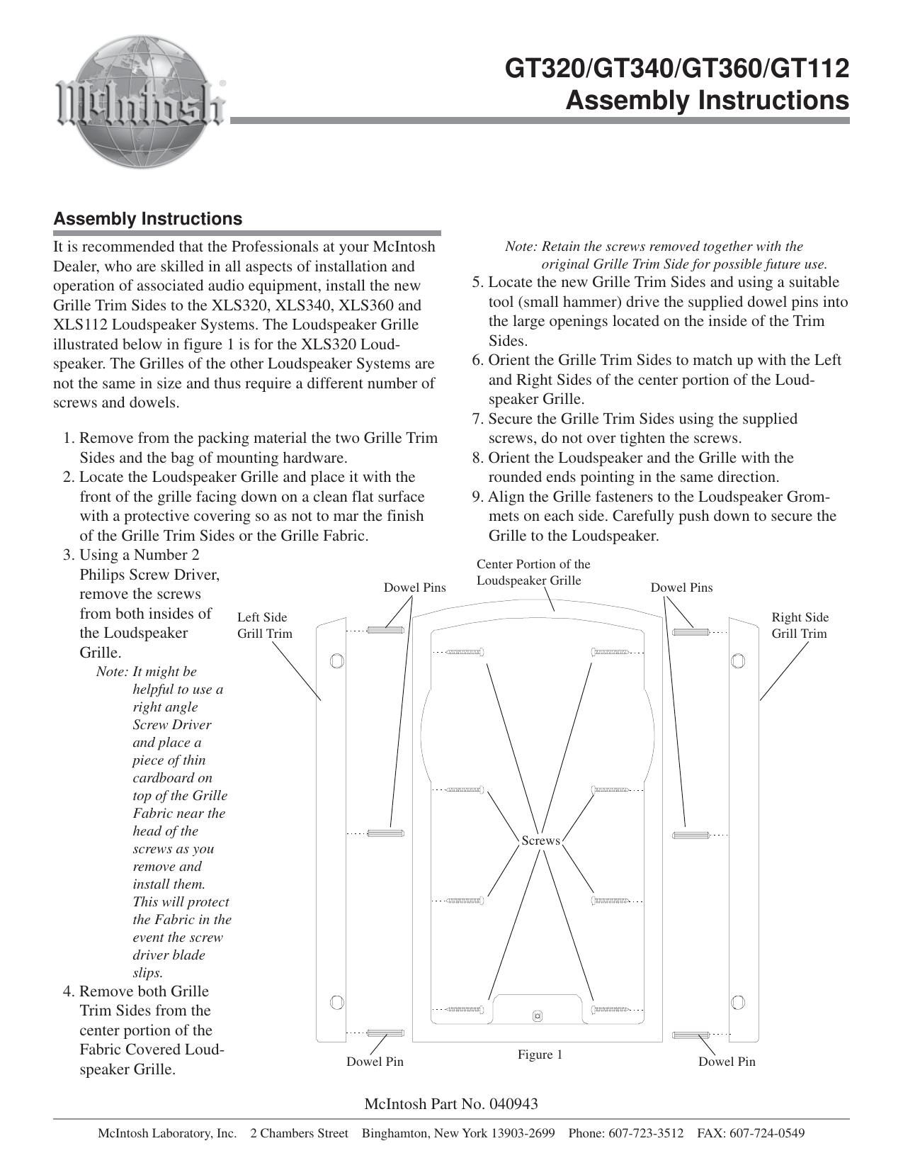
McIntosh Laboratory, Inc. 2 Chambers Street Binghamton, New York 13903-2699 Phone: 607-723-3512 FAX: 607-724-0549 GT350 Assembly Instructions It is recommended that the Professionals at your McIntosh Dealer, who are skilled in all aspects of installation and operation of associated audio equipment, install the new Grille Trim Sides to the XCS350 Loudspeaker System. Re- fer to figure 2. 1. Remove from the packing material the two Grille Trim Sides and the bag of mounting hardware. 2. Locate the Loudspeaker Grille and place it with the front of the grille facing down on a clean flat surface with a protective covering so as not to mar the finish of the Grille Trim Sides or the Grille Fabric. 3. Using a Number 2 Philips Screw Driver, remove the screws from both insides of the Loudspeaker Grille. Note: It might be helpful to use a right angle Screw Driver and place a piece of thin cardboard on top of the Grille Fabric near the head of the screws as you remove and install them. This will protect the Fabric in the event the screw driver blade slips. 4. Remove both Grille Trim Sides from the center portion of the Fabric Covered Loudspeaker Grille. Note: Retain the screws removed together with the original Grille Trim Side for possible future use. 5. Locate the new Grille Trim Sides and using a suitable tool (small hammer) drive the supplied dowel pins into the large openings located on the inside of the Trim Sides.6. Orient the Grille Trim Sides to match up with the Left and Right Sides of the center portion of the Loud- speaker Grille. 7. Secure the Grille Trim Sides using the supplied screws, do not over tighten the screws. 8. Orient the Loudspeaker and the Grille with the rounded ends pointing in the same direction. 9. Align the Grille fasteners to the Loudspeaker Grom- mets on each side. Carefully push down to secure the Grille to the Loudspeaker. Assembly Instructions Figure 2 Right Side Grill Trim Left Side Grill Trim Center Portion of the Loudspeaker Grille Screws Screws Dowel Pins Dowel Pins