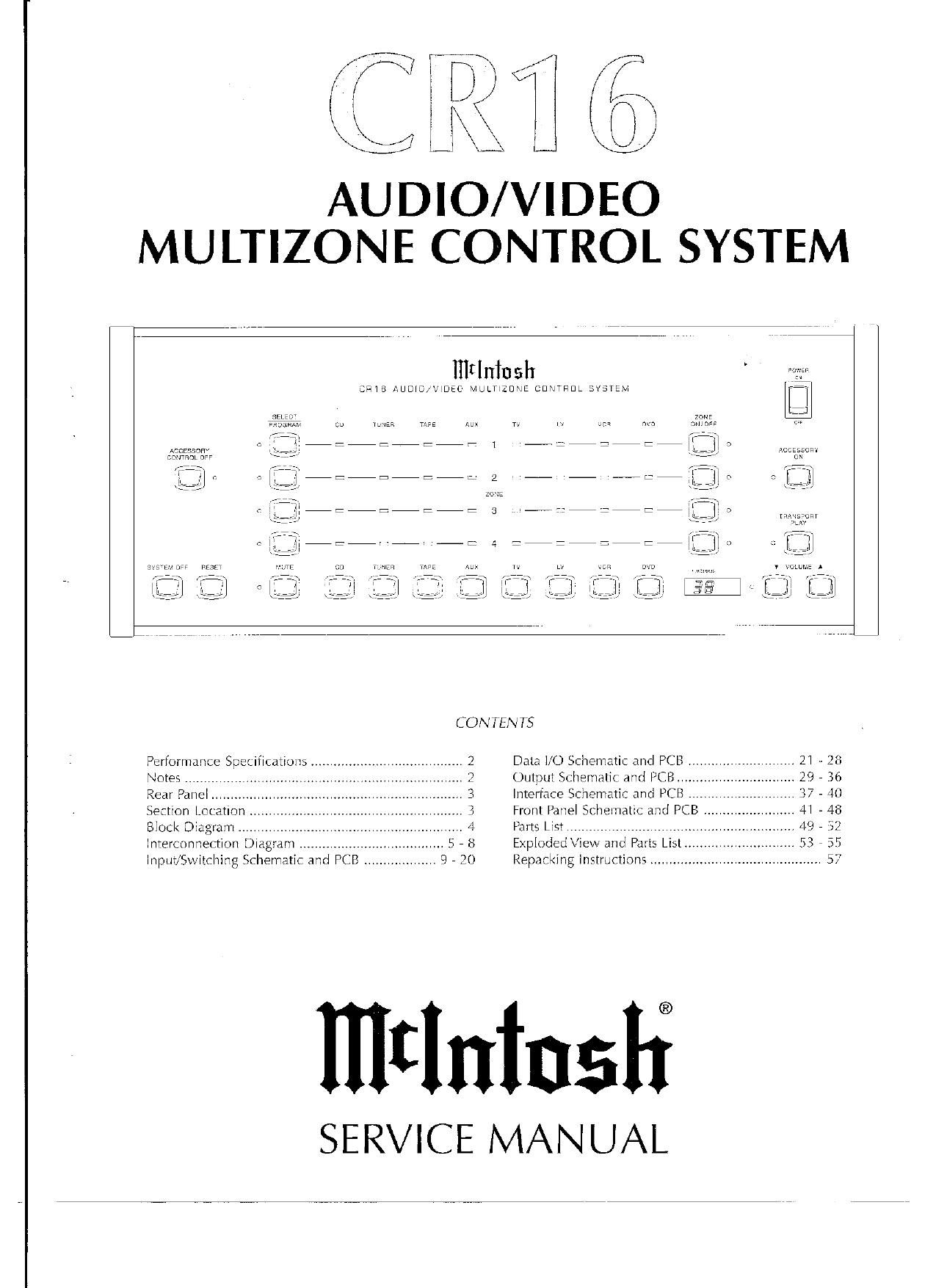
McIntosh CR 16 Service Manual

This is the 58 pages manual for McIntosh CR 16 Service Manual.
Read or download the pdf for free. If you want to contribute, please mail your pdfs to info@audioservicemanuals.com.

Page: 1 / 58
left right
McIntosh CR 16 Service Manual

Extracted text from McIntosh CR 16 Service Manual (Ocr-read)


Page 1

AUDIO/VIDEO
MU LTIZONE CONTROL SYSTEM

CRIB AUDIO/x

zanz
mum-


CONTENTS
Performance Speuflcanuns ....................................... '3 DaIa I10 dematw and PCB ............................ L] - 26
Notes ...... Output Sthematic and PCP; .V 29 , Kb
Rear Pane

Interface SLhemafir and PCB .
Front Panel Schemang and PCB
Pans LIST ,,,,,,,,,,,,,,,,,,,,,,,,,
EprDdedView and Parts L15
Repacking Instructions. ,,,,,,,

IIIIInInsIf

SERVICE MANUAL

Section Location
BIock Diagram .................
Interconnection Diagram .
Input/Switching SChernatIc and PCB

Page 2

PERFORMANCE SPECIFICATIONS

Frequency Response
+0, -0.5dB from ZOHZ to 20,000Hz

Total Harmonic Distortion
0.01% maximum from ZOHZ to 20.000Hz, all
channels at rated output

Signal To Noise Ratio (A Weighted)
90dB below rated output

Rated Output Voltage
1 25 V

Maximum Output Voltage
6V from 20Hz to 20.000Hz

Sensitivity
All inputs. 0.25V for 1.25V rated output

Input Impedance
22k 0th

Maximum Input Signal
8V

Voltage Gain
Input to Variable Outputs 14dB
Input to Fixed (Balanced) Outputs OdB

Tone Controls
Bass and Treble 12dB boost or cut (Level controls
at center detent)

Power Requirements
120 Volts, 50/60Hz at 35 watts

Dimensions
17»1/2 inches (44,5cm) Wide, 7-1/16 inches
(17.9cm) High. 14-1/2 inches (36.8cm) Deep

Weight
272 pounds (12.2 kg) net, 395 pounds (18 kg) in
shipping carton

NOTES

. The heavy notes on the schematic denote the primary
signal path.

. Unless otherwise noted. all voltages indicated on the

schematics are measured under the following conditions:

3. AC input at 120 volts. 50/60Hz.
b. All voltages are +/-10% with respect to ground. A
high impedance (10 megaohrn) voltmeter must be used.

, Unless otherwise specified:
a. Resistor values are in ohms.
b. Capacitor values are microfarads (uF).
c. Inductor values are in microhenries (uH).

to

4. On PC board drawings, Square pad indicates:

a. Polarized Capacitors - Positive
b. Diodes - Cathode
c. Others - Pin ]

WARNING

Parts marked with the symbol have critical
characteristics, Use only replacement parts recom-
mended by the manufacturer.

Use McIntosh Remote Control Model HRLO42 with the
CR 1 6.