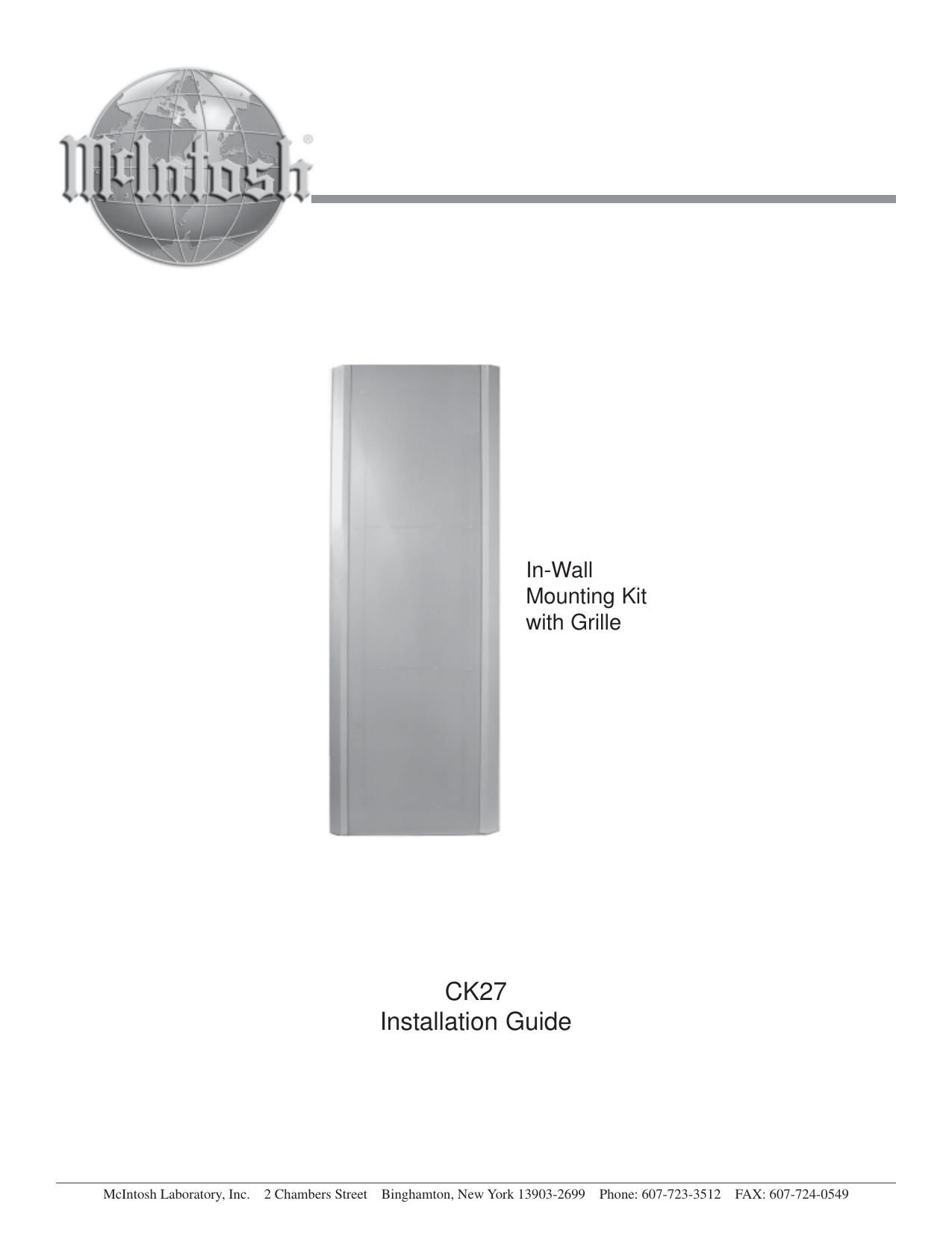
McIntosh CK 27 Owners Manual

This is the 4 pages manual for McIntosh CK 27 Owners Manual.
Read or download the pdf for free. If you want to contribute, please mail your pdfs to info@audioservicemanuals.com.

Page: 1 / 4
left right
McIntosh CK 27 Owners Manual

Extracted text from McIntosh CK 27 Owners Manual (Ocr-read)


Page 1

2 Installation The XR27 Loudspeaker System requires two or more per- sons to safely handle during assembly and placement. If the CK27 In-Wall Mounting Kit with Grille is for install- ing an unboxed XR27, proceed to Unpacking the Loud- speaker step number 17. When the XR27 location is changing from an On-wall to an In-wall Mounted Installa- tion proceed to Removing the Loudspeaker from the On - Wall Vertical MountingWall step number 1 or Removing the Loudspeaker from the On-Wall Horizontal MountingWall step number 8. It is recommended that the Professionals at your McIntosh Dealer, who are skilled in all aspects of installation and operation, install the XR27 Loudspeaker System and any associated audio equipment. Removing the Loudspeaker from the On-Wall Vertical Mount 1. Carefully remove the XR27 Loudspeaker Grille from the Loudspeaker and place it in a safe location. 2. Remove the long Locking Screw from the Wall Mounting Bracket located at the top of the XR27. Refer to figures 1 and 2. 3. Remove the XR27 from the wall by grasping both sides of the Loudspeaker and lifting first straight up about six inches, then away from the wall. 4. Temporarily set the Bottom of the Loudspeaker on the floor and dis- connect the hookup cables. 5. Place the XR27 on the shipping carton, if still available, or on another suitable object so the Loudspeaker is about a foot off the floor. Refer to figure 9 on page 3. 6. Using the supplied Allen Wrench remove the Mounting Bracket from the top of the Loud- speaker by removing the screw. Install one screw (1/4-³ x 20 Flat Head) into the opening at each end of the Loudspeaker. Refer to figure 3. Important Information Caution: The XR27 Loudspeaker System weight is 84 pounds (38kg) net. It requires two or more persons to safely handle. Figure 2 Note: This is very important to prevent air leaks from the Loudspeaker Enclosure. 7. Remove the Wall Bracket from the wall. Note: Save the just removed screws and Wall Bracket for possible future use. 8. Proceed to Installing the Loudspeaker System step number 27. Removing the Loudspeaker from the On-Wall Horizontal Mount 9. Carefully remove the XR27 Loudspeaker Grille from the Loudspeaker and place it in a safe location. 10. With two persons supporting the XR27 Loudspeaker, slowly raise the Loudspeaker together with the attached Wall Hanger Bracket straight up until the bottom of the loudspeaker has cleared the Wall Bracket. Refer to figure 4. 11. Disconnect the hookup cables. 12. Place the XR27 on the shipping carton, if still avail- able, or on another suitable object so the Loud- speaker is about a foot off the floor. Refer to figure 9 on page 3. 13. Using the supplied Allen Wrench and remove the Wall Hanger Bracket from the XR27 Loudspeaker. Refer to figure 5 Note: Save the just removed screws and Wall Hanger Bracket for possible future use. 14. Install four screws (1/4-³ x 20 Flat Head) into the openings vacated by removal of the Wall Hanger Bracket. Refer to figure 6. Note: This is very important to prevent air leaks from the Column Enclosure. 15. Remove the Wall Bracket from the wall. Note: Save the just removed screws and Wall Bracket for possible future use. Install Screw Install Screw Figure 6 Install Screw Figure 3 Figure 4 Figure 5 12345 1234 5 1 234 5 1 234 5 1 234 5 1 234 5 1 234 5 1 234 5 1 234 5 1 234 5 1 234 5 1 234 5 1 234 5 1 234 5 1 234 5 1 234 5 1 234 5 1 234 5 1 234 5 1 234 5 1 234 5 1 234 5 1 234 5 1 234 5 1 234 5 12345 Locking Screw Wall Column Top Wall Bracket Figure 1

Page 2

3 Installation 16. Proceed to Installing the Loudspeaker System step number 27. Unpacking the Loudspeaker 17. Remove the banding material from the shipping car- ton. Refer to figure 7. 18. Lift off the top of the shipping carton and set it aside. 19. Lift up on the rear of the Loudspeaker Sys- tem, near the foam packing material at both ends. Place the entire assembly (Loud- speaker System, Loud- speaker Grille, On- Wall mounting brack- ets and foam packing material) next to the bottom shipping carton on a flat surface. Refer to fig- ure 8. 20. Release the Loudspeaker Grille from the packing ma- terial by opening the slit in the packing material lo- cated on the top center. Remove the Loudspeaker Grille from the protective shipping wrap and set it aside. 21. In a similar manner, lift out the Loudspeaker System and set it aside. 22. Replace the shipping carton top onto the shipping carton bottom. Take the two center pieces of the just removed packing material and lay it down flat onto the top of the shipping carton. 23. Carefully remove the protective shipping bag(s) from the Loudspeaker System so as not to mar the finish or damage the Loudspeaker System Drivers. 24. Place the Loudspeaker System, with the front facing down, on top of the packing material located on top of the shipping carton. Refer to figure 9. 25. Remove the four screws securing the Stabilizer Bar to the back of the XR27 Loudspeaker System. Refer to figure 10. Note: Save the just removed Stabilizer Bar and screws for possible future use. 26. Using the supplied Allen Wrench and hardware, in- stall four screws (10/32-³ - 3/4 Allen Head) into the openings vacated by the removal of the Stabilizer Bar. Installing the Loudspeaker System The XR27 Loudspeaker Systems Smooth Frequency Re- sponse may be altered by large object(s) lo- cated in sound waves path or by locating the column too close to a side wall. There should be an unobstructed area in front of the col- umn of at least 15 de- grees either top or bot- tom from the center axis for the best performance. Refer to figure 11. 27. Use a suitable wall stud finder or metal detector to verify a proper mounting location for the Loud- speaker System before cutting into the wall. The CK27 is designed for attaching to wall headers with 16 inch (40.64cm) centers. Refer to figure 12. Note: Make sure there are no Plumbing Pipes, AC Electrical Wiring or Heating/Cooling Ductwork in the wall between the studs where the Loudspeaker Column is to be mounted. Figure 7 Figure 8 Figure 9 Packing material Stabilizer Bar Screws Stabilizer Bar Figure 10 Figure 11 Figure 12