McIntosh C20 Owners Manual 2

This is the 20 pages manual for McIntosh C20 Owners Manual 2.
Read or download the pdf for free. If you want to contribute, please mail your pdfs to info@audioservicemanuals.com.

Page: 1 / 20
left right
McIntosh C20 Owners Manual 2

Extracted text from McIntosh C20 Owners Manual 2 (Ocr-read)


Page 1

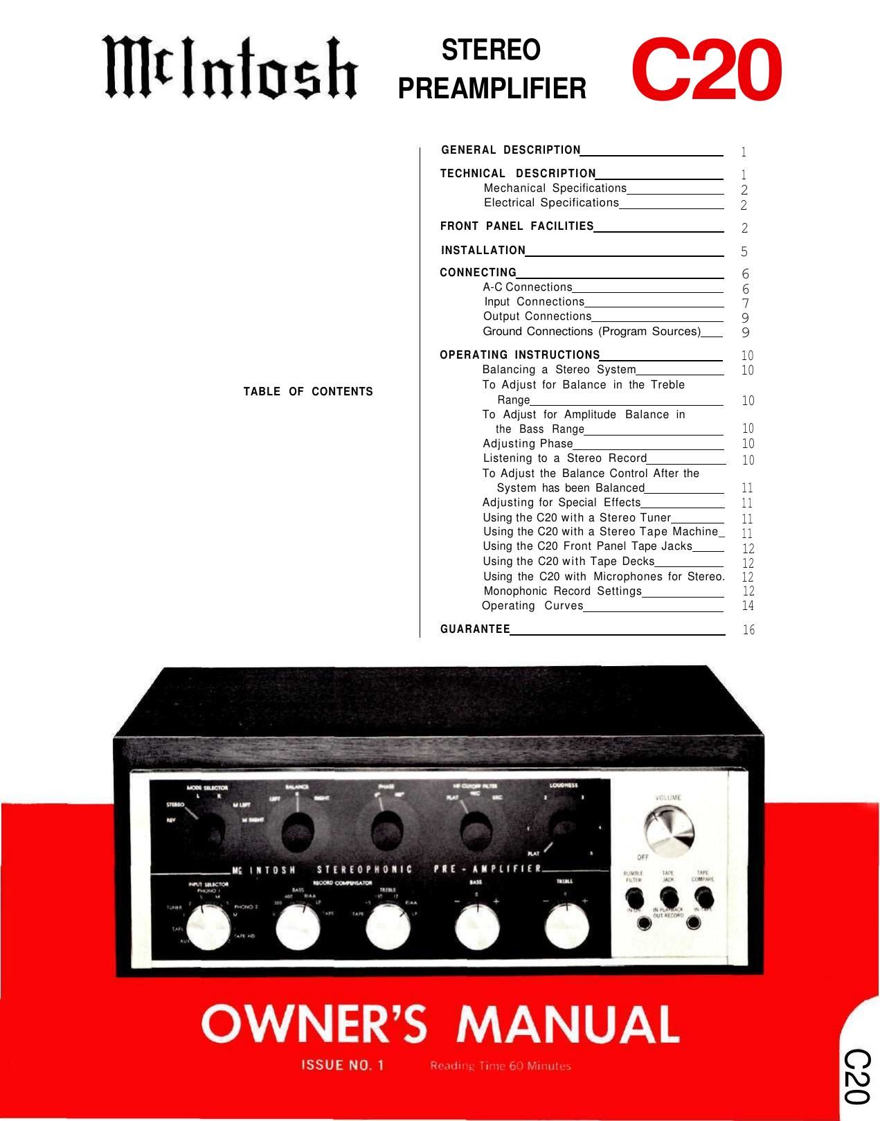
mt IUIU 5 I1 PRESAIMIIIIIZEICFIER

GENERAL DESCRIPTION

1
TECHNICAL DESCRIPTION 1
Mechanical Specifications 2
Electrical Specifications- 2
FRONT PANEL FACILITIES 2
INSTALLATION 5
CONNECTING 6
A-C Connections 6
Input Connections 7
Output Connections 9
Ground Connections (Program Sources)i 9
OPERATING INSTRUCTIONS 10
Balancing a Stereo System 10
TABLE OF CONTENTS To Adjust for Balance in the Treble
Range 10
To Adjust for Amplitude Balance in

the Bass Range 10
Adjusting Phase 10
Listening to a Stereo Record 10

To Adjust the Balance Control After the
System has been Balanced 11
Adjusting for Special Ellects- 11
Using the 020 With a Stereo Tuner 11
Using the 020 with a Stereo Tape Machinei 11
Using the 620 Front Panel Tape Jacks 12
Using the (320 with Tape Decks 12
Using the 020 With Microphones tor Stereo. 12
Monophonic Record Settings 12
Operating Curves 14
GUARANTEE 16

IGIIIDSH SIIRiOPHOIIC FIE-AIPtIflEII

mm

m mm nu III-A

03C)

Page 7

VOLUME

VOLUME

OFF

The combined VOLUME control and OFF-on
switch controls the volume for both channels and
switches line power to four black receptacles on the
back panel.

LOW FREQUENCY TRIM

LOW razoumcv TRIM

0 0
@ @
m

These controls, located on the back panel, com-
pensate for unequal speaker response at low frequen-
cies due to location of speakers in a room or differ-
ences in speaker efficiency. It provides 6db boost at
50 cycles starting from 500 cycles or 8db cut at 20
cycles starting from 200 cycles.

INSTALLATION

The 020 can be installed in conventional cabinets,
custom built-ins, or professional equipment racks. If
the unit is to be placed on a shelf or table-top, it is
recommended that it be housed in a McIntosh Model
L-66 cabinet. Install the 020 from the front of the
cabinet; not from the rear.

When mounting the 020 the minimum thickness
of wood panel should be 1/4" in order to support the
weight. Panels up to 1" thickness may be used. If the
front panel of a cabinet is made of wood, to prevent
warping a shelf is required to support the rear of the
chassis. When mounted on a metal rack panel, a shelf
is not needed.

The C20 installation should allow at least 13-3/4"
behind the front panel to allow about 1-1/2" for con-
nectors. The desireable width and height are, 16-1/2"
and 5-1/2", respectively, so there* will be sufficient
space for circulation of air. These are inside dimensions.
The front panel mounting space width and height
are 16-3/3" and 5", respectively.

MAKING THE FRONT PANEL CUTOUT

The panel is cut out using the "FRONT PANEL
CUTOUT TEMPLATE." To position the template on the
front of the panel, make two locating holes from the
back (inside) of the panel using one of the mounting
strips (1/2" by 3-1/2") as a measuring tool. Proceed as
follows:

Determine the exact center of the proposed cutout
area. Scribe a vertical center line from the top of the
panel to the top surface of the shelf as illustrated in
"A Figure 2. Using one of the mounting strips as a
measuring tool, draw a horizontal line 3-1/2" above the
shelf. (See "",B Figure 2.) Place a mounting strip along
the horizontal line to the left of the vertical center line
and mark a point 3-1/2" left from the vertical center
line. Repeat this procedure and mark a point 3-1/2" to
the right of the vertical center line. These points should
now be 3-1/2" up from the top of the shelf and 7"
apart, one 3-1/2" to the left and one 3-1/2" to the right
of the vertical center line. (See "",C Figure 2.) Drill a
3/16" hole at each point. Hold the drill perpendicular
to the panel so that the hole will be located accurately
on the front of the panel.

Position the template on the front of the panel
using the two locating holes to line it up correctly.
Scribe the rectangular opening on the front panel and
mark the position of the six mounting holes. Drill the
six 3/16" mounting holes before cutting the panel
opening. Then cut out the opening. It is important that
the cutout be just within the lines.

SHELF MOUNTING

It the installation requires a shelf, proceed as

A VERTICAL CENTER LINE

Positions "A to "C show the location of the
vertical center line, the use of the measuring
tool (mounting strip) to locate the horizontal
center line, and how to measure off the two
points to the right and left of the vertical
center line.

Figure 2. Cutout Measurements

Page 16

RESPONSE IN D8

14

RESPONSE IN OB

OPERATING CURVES


A TOTAL OF 25 E
ARE POSSIBLE, THE ABOVE SHOWS SE

OF THE MOST USED CURVES.

QUALIZATION COMBINATIONS
VER

)>
,_

425
20 100 1 KC 10 KC 20 KC
FREQUENCY
Figure 10. RECORD COMPENSATOR Controls
- - BASS, MAX. AND MIN. RANGE
20
\ - - - - TREBLE, MAX. AND MIN. RANGE
15 T. \
~ _. __
T \\ a a
10 N a
\ \ z W
4 r
5 \ /
T \ . z
_ __ _ .71-4
0 - EN; 4
, " \ \
75 / / \ \
4 ~
/ x \
-10 N
N~
/ \
45 / I x
a/ / \
-2o -
20 100 IKC 10 KC 20 KC
FREQUENCY

Figure 11. BASS and TREBLE Controls

Page 18

Your 020 will give you many years of pleasant and satisfactory
performance. If you have any questions concerning the operation
or maintenance of this pre-amplifier please contact:

Customer Service

McIntosh Laboratory Inc.
2 Chambers Street
Binghamton, New York
Our telephone number is 7235491.
The direct dial area code is 607.

GUARANTEE

McIntosh Laboratory Incorporated guarantees this
equipment to perform as advertised. We also guarantee
the mechanical and electrical workmanship and com»
ponents of this equipment to be free of defects for a

period of 90 days from date of purchase. This guaran-
tee does not extend to components damaged by im»
proper use nor does it extend to transportation to and
from the factory.

3-YEAR FACTORY SERVICE CONTRACT

An application for a FREE 3-YEAR FACTORY
SERVICE CONTRACT is included in the pocket in the
back cover of this manual. The FREE 3-YEAR FACTORY
SERVICE CONTRACT will be issued by McIntosh Lab»
oratory upon receipt of the completely filled out appli-
cation form. The term of this contract is defined in the

3»year factory service contract. If the application is not
mailed to McIntosh Laboratory, only the services offered
under the standard 90-day guarantee will apply on this
equipment. TAKE ADVANTAGE OF 3 YEARS OF FREE
FACTORY SERVICE BY FILLING IN THE APPLICATION
NOW.

In Canada: manufactured under license by:
McCurdy Radio Industries, Ltd.
22 Front Street West

Toronto. Canada

16

Design subject to change without notice.