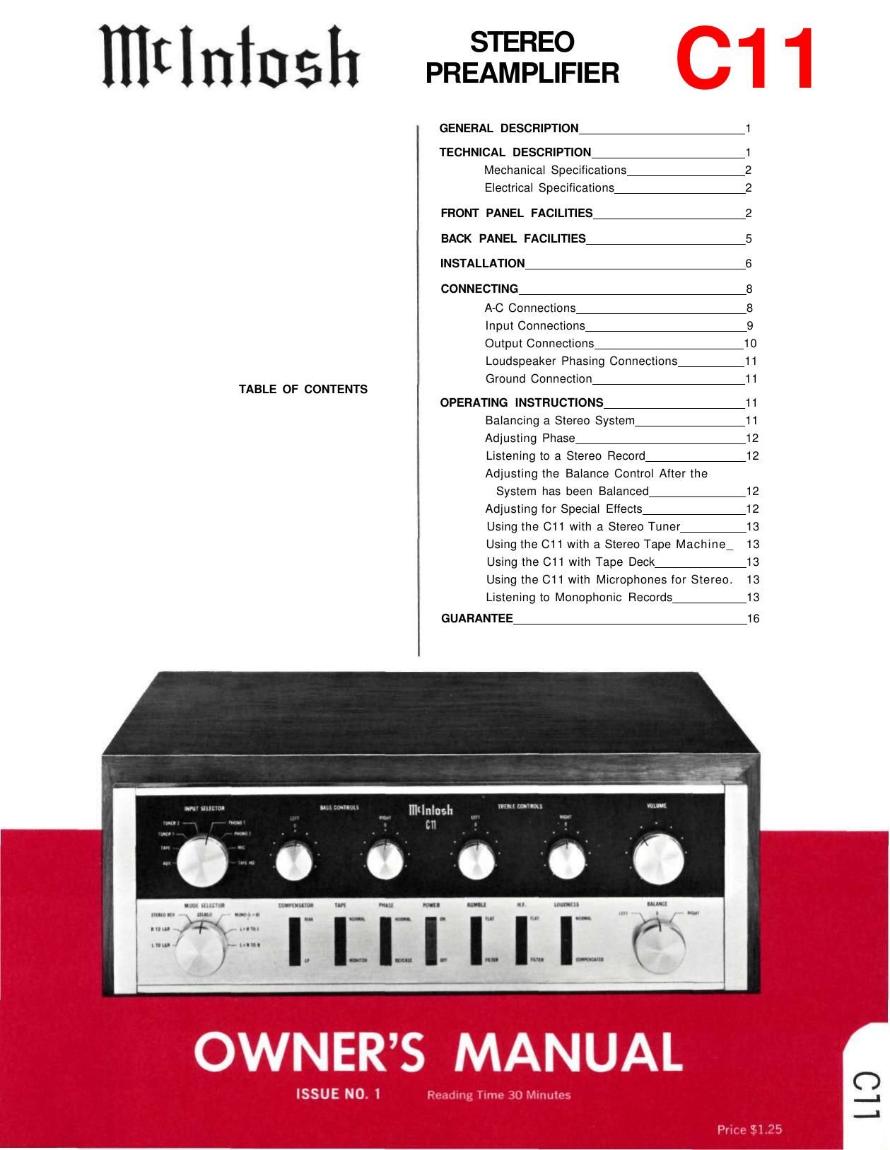
McIntosh C11 Owners Manual

This is the 20 pages manual for McIntosh C11 Owners Manual.
Read or download the pdf for free. If you want to contribute, please mail your pdfs to info@audioservicemanuals.com.

Page: 1 / 20
left right
McIntosh C11 Owners Manual

Extracted text from McIntosh C11 Owners Manual (Ocr-read)


Page 1

Page 2

C11 STEREOPHONIC PREAMPLIFIER GENERAL DESCRIPTION The Mcintosh C11 Stereophonic Pre­ amplifier is a control center for any stereo­ phonic sound system. To increase the enjoyment of stereo, this control center does four jobs with precise control. First, the control center amplifies weak electrical impulses. As the record rotates on the turntable, undulations in the grooves move the pick-up stylus approximately one- thousandth of an inch, in any direction, from the rest position. From this slight mechanical movement, the pick-up stylus generates a weak electrical impulse on the order of a few thousandths of a volt. To amplify and pre­ serve the information in such an electrical impulse, the finest amplifier performance is required. Second, every sound system is used in a different acoustical environment. The tone balance of the music is affected by variations The C11 Stereophonic Preamplifier com­ bines excellence in performance with ease of operation. The controls used the most have large diameter knobs. A new type of rocker switch indicates those controls with simple off-on functions. The C11 has an illuminated front panel with light intensity control to provide convenient reading under low-level lighting conditions. The C11 circuit consists of three amplify­ ing sections in duplicate for the left and right stereo channels and a power supply. The first section is the input preamplifier used to amplify and equalize the input signals com­ ing from phonograph pickups, microphones, or tape heads. Skillful layout, grounding, and shielding for low hum pickups, metal film and wire wound resistors, terminal boards with high specific resistivity, low noise tubes and extreme care in manufacturing combine to achieve a new low in noise and hum. The second amplifying section follows the volume control, and thus it is impossible to overload the circuit or any following circuits. The same techniques as were used in the preamplifier stage assure low hum and noise. The bass and treble tone controls are feed­ back type circuits and operate in connection in environment. Also, people listening to the music have varying ideas of correct tone bal­ ance. To compensate for these conditions, a high-quality control center is needed. Third, there is a great variety of stereo­ phonic and monophonic records manufac­ tured today, both domestic and foreign. The control center must accurately compensate for the equalization introduced in the re­ cording process. Fourth, with programs originating from several sources such as tuners, records, tape machines, microphones, etc., a control cen­ ter is needed to select and switch these sources separately or in combination. All of these jobs are performed with ex­ cellence by the C11 and yet this instrument is simple to operate, easy to mount, and is the finest in appearance. with this section. Exceedingly low distortion and correct frequency response are assured using this arrangement. The third section is the cathode follower output. The sharp cut-off (18db per octave) rumble and high frequency filters are asso­ ciated with this section. Output level set con­ trols are located at the input of the cathode follower to allow simple balance of the entire amplifying and speaker system. These con­ trols are conveniently accessible at each side of the front panel under the end caps. The power supply deserves special men­ tion. The power transformer is constructed with "core" type grain oriented laminations and magnetic shielding for low hum field. Long life rectifiers, full wave rectification, filter condenser sectionalizing and careful grounding add to the hum free and long life characteristics of the C11. Special attention has been given to the mechanical design also. The C11 may con­ veniently be installed in furniture cabinets, custom built installations, or professional relay racks. The tubes and the electrical con­ nections are conveniently located on the back panel of the C11 for ready access. 1 TECHNICAL DESCRIPTION

Page 12

11 treble response, turning it counterclockwise decreases the treble response. Use the con­ trols to compensate for 3% tape speed for individual tape head characteristics. A left plus right output jack is next to the MAIN output. It is marked L+R. A mono­ phonic signal can be distributed to other rooms by connecting a third power amplifier to the jack marked L+R. This amplifier is used to drive the monophonic loudspeakers. The cable connecting to this output should not have a capacity of more than 200 mmf. The input impedance of the power amplifier connecting to this output should not be less than 150,000 ohms (150K). The generator impedance at this output is approximately 25,000 ohms (25K). LOUDSPEAKER PHASING CONNECTIONS Two pairs of screw terminals are located on the lower left section of the C11 back panel. The speaker leads from the "left" power amplifier should be connected to the screw terminals marked FROM AMPLIFIER. The pair of terminals marked TO SPEAKER The ultimate in stereo performance and listening enjoyment is obtained through the proper balancing of the stereo system. A properly balanced stereo system must be in phase. Each channel must be equal in loud­ ness and similar in frequency response. Do not use the C11 BALANCE control for this procedure. The C11 BALANCE control is used to adjust for any unbalance in the source material, the phono cartridge, and tape machine. Before attempting the balancing of the C11 make sure the controls on the amplifiers are set properly. On the MC240 and MC275 turn the control marked BALANCE to its center position. On the MC225 set the input level controls for each channel to the black dot above the control. To properly balance the C11, proceed as follows: A familiar recording, either stereo­ phonic or monophonic, should be used in balancing the C11. 1. Turn the INPUT SELECTOR to the posi­ tion corresponding to the program selected. 2. Turn the BASS CONTROLS and TREBLE CONTROLS to their 0 positions. 3. Turn the MODE SELECTOR to the L+R TO L position. 4. Place the COMPENSATOR switch in the RIAA position. 5. Place the TAPE switch in the NORMAL position. 6. Place the PHASE switch in the NORMAL position. 7. Place the POWER switch in the ON position. 8. Place the RUMBLE switch in the FLAT position. 9. Place the H.F. cutoff filter switch in the FLAT position. 10. Place the LOUDNESS switch in the NORMAL position. 11. Turn the BALANCE control to the 0 position. 12. While the program is playing, alternate the MODE SELECTOR between the L+R TO L position and the L+R TO R position. Adjust the thumb wheel level controls under the end caps until the loudspeakers are of equal loudness. When the proper balancing of the Mcin­ tosh C11 is accomplished, the stereo system will remain balanced throughout all modes of operation. OPERATING INSTRUCTIONS BALANCING A STEREO SYSTEM should be connected to the "left" loud­ speaker. These connections allow the front panel PHASE switch to reverse the phase on the left loudspeaker. This arrangement is con­ venient when setting up a stereo system. GROUND CONNECTION A single ground post is provided. The chassis ground from turntable, record chang­ ers (motors used with each), tape decks, etc., should be returned to this post. Do not dupli­ cate this ground circuit. Hum is likely to be heard in the system if duplicate ground re­ turns are used. The left and right program cables from each source should be twisted together and the ground wire from each source can be wound or twisted in with these cables. To avoid hum, make sure the ground wire does not make any connections to shields of the left and right channel cables except for the connection provided with the C11 ground post.