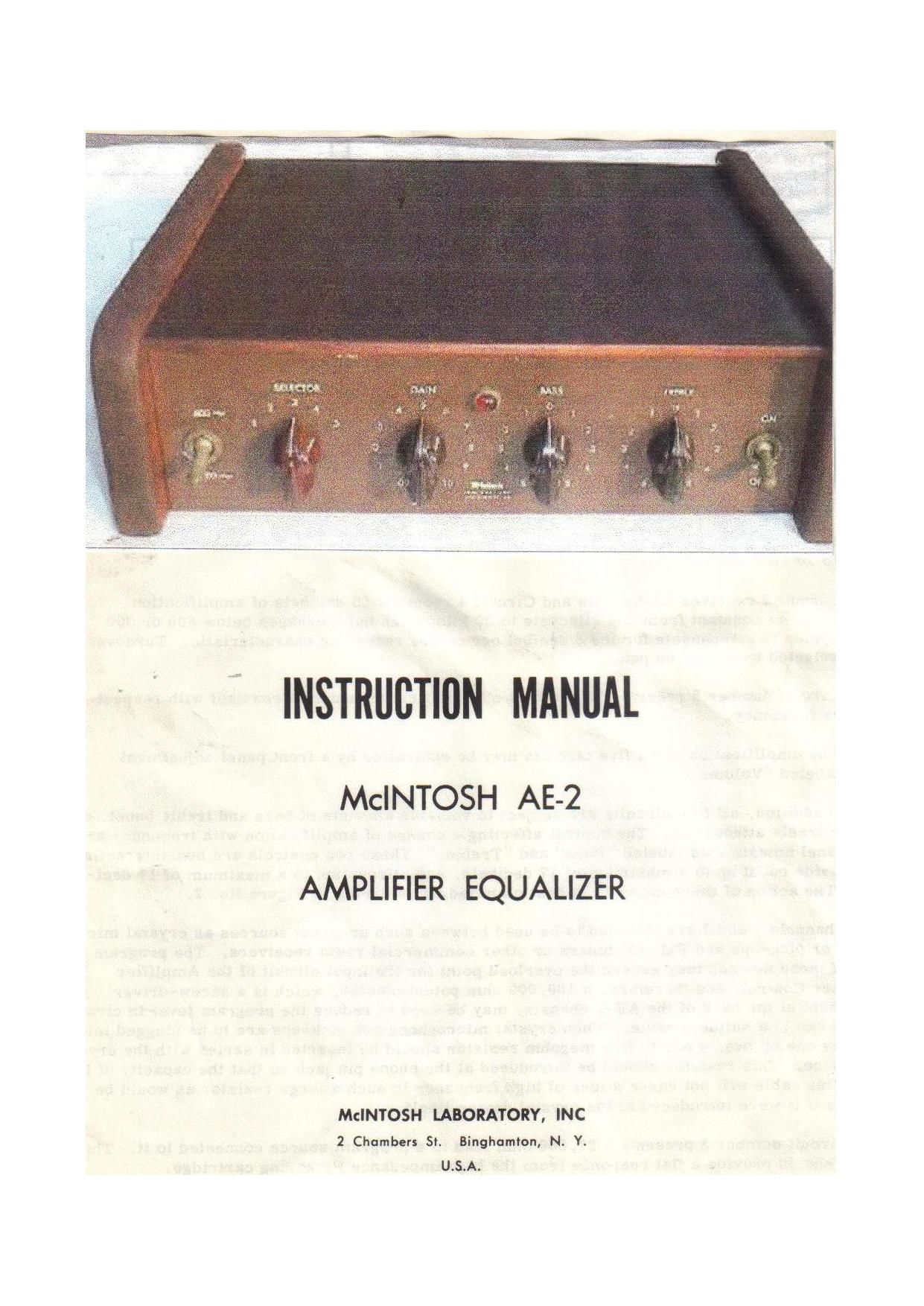
McIntosh AE 2 Owners Manual

This is the 4 pages manual for McIntosh AE 2 Owners Manual.
Read or download the pdf for free. If you want to contribute, please mail your pdfs to info@audioservicemanuals.com.

Page: 1 / 4
left right
McIntosh AE 2 Owners Manual

Extracted text from McIntosh AE 2 Owners Manual (Ocr-read)


Page 1

INSTRUCTIBN MANUAL

McINTOSH AE-2

AMPLIFIER EQUALIZER

McINTOSH lABORATORY, INC
2 Chambers 5'. Binghamlon, N. Y.
U.S.A.

Page 2

INSTRUCTION BOOK
FOR THE
MODEL AE-Z AMPLWIER EQUALIZER CONTROL

The McINTOSH AE-2 AMPLIFIER EQUALIZER CONTROL has been designed for the home
user primarily to give him a real professional quality instrument and to permit a stable and
distortionless equalization and amplification to suit the listener's discriminating taste and to
accommodate, we believe, all known phonograph recordings and to permit in most cases, pick-
up from magnetic tape machines. Reasonable care is always necessary to keep the unit operat-
ing indefinitely and delivering excellent quality for all positions of the controls. Access to the
bottom of the unit is by removal of a screw in the bottom plate and the top is accessible by
sliding the plywood panel back and removing the metal shield cover underneath the plywood
panel. This will enable the procedure of checking and servicing the unit.

The Model AE-Z Amplifier Equalizer Control is intended to provide an adequate amount of
amplification between five different program sources and a McIntosh 50 or 20 watt power am-
plifier. The various program circuits may be selected by means of a front panel control
labeled "Selector. " Reference to the schematic diagram shown in Figure 1 will be of assistance
in following the description. Y

Circuits l and 2 receive 50 decibels of amplification which is constant from 20 cycles

to 20 kilocycles.

Circuit 3 receives 40 decibels and Circuit 4 receives 50 decibels of amplification
which is constant from one kilocycle to 20 kilocycles but increases below 600 or 300
cycles to compensate for the 6 decibel per octave recording characteristic. Turnover
selected by switch on panel.

Circuit number 5 receives 75 decibels of amplification which is constant with respect
to frequency.

The amplification of all five circuits may be controlled by a front panel adjustment
labeled "Volume. "

In addition, all five circuits are subject to variable amounts of bass and treble boost. or
bass or treble attenuation. The control affecting a change of amplification with frequency are
front panel adjustments labeled "Bass" and "Treble. " These two controls are non-interacting
and provide boost up to a maximum of 17 decibels, and attenuation to a maximum of 17 deci-
bels. The action of these controls is best clarified by referring to Figure No. 2.

Channels 1 and 2 are intended to be used between such program sources as crystal micro-
phones or pick-ups and FM-AM tuners or other commercial radio receivers. The program
level of these devices may exceed the overload point for the input circuit of the Amplifier
Equalizer Control, and therefore, a 100, 000 ohm potentiometer, which is a screw-driver
adjustment at the back of the AE-Z chassis, may be used to reduce the program level in circuits
one and two to a suitable value. When crystal microphones or pick-ups are to be plugged into
channels one or two, a one to five megohm resistor should be inserted in series with the cry-
stal device. This resistor should be introduced at the phono pin jack so that the capacity of the
connecting cable will not cause a loss of high frequency in such a large resistor as would be
the case if it were introduced at the crystal device itself.

Circuit number 3 presents a 27. 000 ohm load to a program source connected to it. This
circuit should provide a flat response from the high impedance Pickering cartridge.

Circuit number 4 presents a 12, 000 ohm load to a program source connected to it. This
circuit should provide a flat response from the GE variable reluctance cartridge.