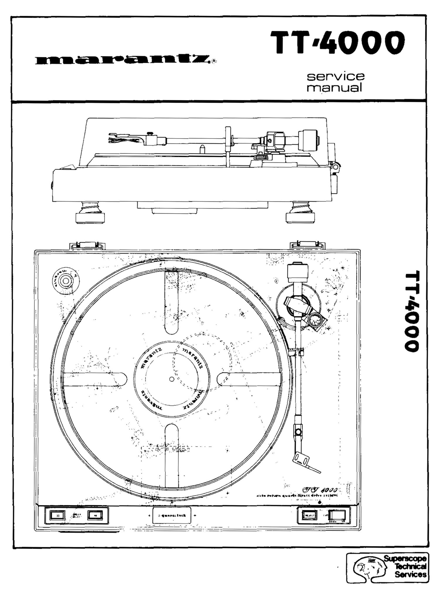
Marantz TT 4000 Service Manual

This is the 13 pages manual for Marantz TT 4000 Service Manual.
Read or download the pdf for free. If you want to contribute, please mail your pdfs to info@audioservicemanuals.com.

Page: 1 / 13
left right
Marantz TT 4000 Service Manual

Extracted text from Marantz TT 4000 Service Manual (Ocr-read)


Page 1

TT'lIOOO

service

00094.1

" ' f2 .
~ _ @67 40am
Ms.- "M gun!!! Biron dflvo in ' j

q) .. b-I ..

Page 2

INTRODUCTION

This service manual was prepared for use by Authorized The parts list in this manual pertains to five different
Warranty Stations and contains service information for areas. Be sure that part numbers for your respective area
a Marantz Semi-Automatic Quartz Lock TT-4000 Turn- are correct before parts orders are placed. A simple des-
table. Serviceinformation and voltage data included in this cription is provided for parts which can be purchased
manual are intended to be used by experienced service locally or through the Marantz Parts Facilities. Refer to
technicians, knowledgeable in Turntable designs and Ser- the Marantz Design and SerVice Section of this manual for
vice. All instructions should be read and no attempt to correct parts ordering methods.

repair the circuits or mechanisms should be made until
complete operation is understood.

TT-4000 SERVICE MANUAL CONTENTS

SUBJECT PAGE
MARANTz DESIGN AND SERVICE ................................... 1
CARTRIDGE WIRE COLOR CODE .................................... 2
STYLUSOVERHANGADJUSTMENT................................2
STYLUS TRACKING FORCE ADJUSTMENT ............................ 2
AUTO-RETURN ADJUSTMENT....................................2
MOTOR REPLACEMENT PROCEDURE ............................... 2
DRIVING WAVEFORM ADJUSTMENT. ............................... 3
CIRCUIT WAVEFORM ANALYSIS ................................... 3
TT-4000 TROUBLE SHOOTING CHART .............................. 4
CHASSIS WIRING ASSEMBLY ...................................... 5
POWER SUPPLY CIRCUIT BOARD ................................... 5
MOTOR CONTROL CIRCUIT BOARD. ................................ 6
CIRCUIT VOLTAGE CHARTS. ...................................... 6
ELECTRICAL SCHEMATIC (Inserted) .................................. 7
TT-4000 MECHANICAL ASSEMBLY (inserted) -------------------------- 8
PARTS LIST .................................................. 940
TT-4ooo TECHNICAL SPECIFICATIONS. ............................. 11

PACKAGING ASSEMBLY . .......................................... ll