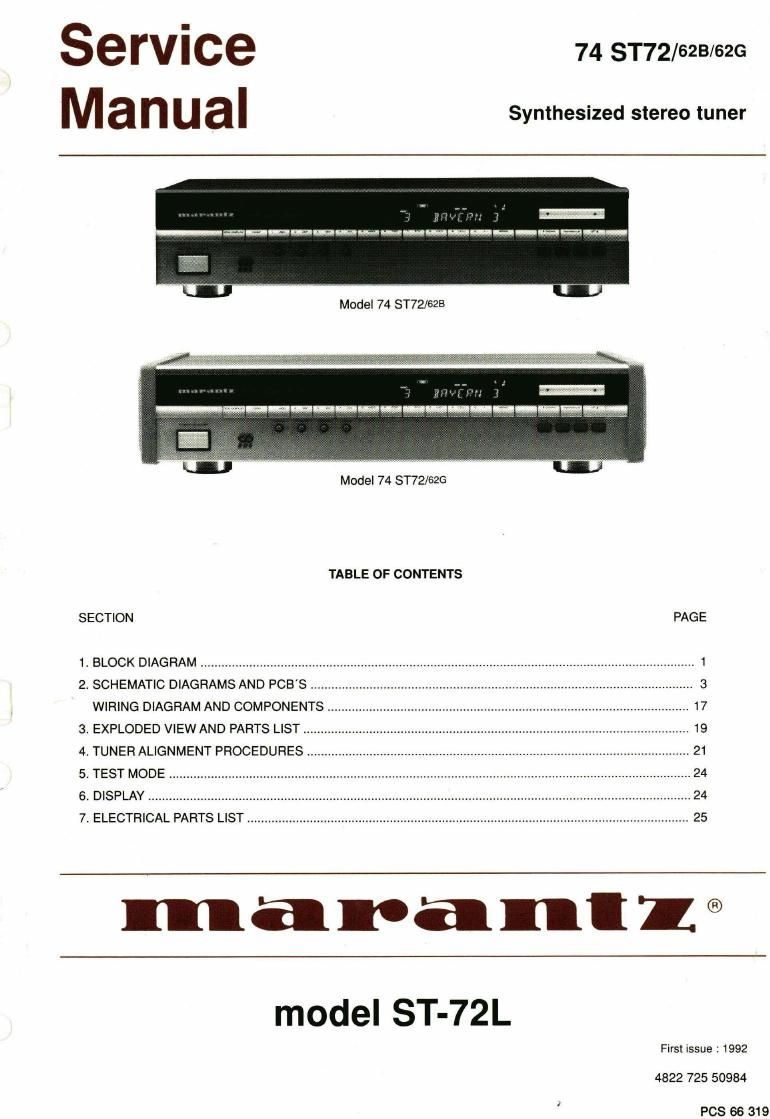
Marantz ST 72 Service Manual

This is the 15 pages manual for Marantz ST 72 Service Manual.
Read or download the pdf for free. If you want to contribute, please mail your pdfs to info@audioservicemanuals.com.

Page: 1 / 15
left right
Marantz ST 72 Service Manual

Extracted text from Marantz ST 72 Service Manual (Ocr-read)


Page 1

SGTVICE 74 ST72/628/62G
M a n U al Synthesized stereo tuner

Model 74 ST72/628

Model 74 ST72/62G

TABLE OF CONTENTS

SECTION PAGE

1. BLOCK DIAGRAM ................................................................................

2. SCHEMATIC DIAGRAMS AND PCB'S
WIRING DIAGRAM AND COMPONENTS

3. EXPLODED VIEW AND PARTS LIST ............................................................................................................... 19
4, TUNER ALIGNMENT PROCEDURES .............................................................................................................. 21
5. TEST MODE ...................................................................................................................................................... 24
6 DISPLAY ........................................................................................................................................................... 24
7. ELECTRICAL PARTS LIST .............................................................................................................................. 25

maranll®

model ST-72L

First issue : 1992

4822 725 50934

PCS 66 319

Page 2

MARANTZ DESIGN AND SERVICE

Using superior design and selected high grade
components, MARANTZ company has created the
ultimate in stereo sound.

Only original MARANTZ parts can insure that your
MARANTZ product will continue to perform to the
specifications for which it is famous.

MAFIANTZ INTERNATIONAL
Vestdiik 9

5600 MD Eindhoven

The Netherlands

Phone: +31/40.758290
Telefax: +31/40.75.82.99

Parts for your MARANTZ equipment are generally
available to our National Marantz Subsidiary or Agent.

ORDERING PARTS:

Telex: 35000 PHTC NL routing IND NLMTFAT

Parts can be ordered either by mail or by telex. In both

cases. correct part number has to be specified. .

The following information must be supplied to eliminate

delays in processing your order:

Complete address

Complete pan numbers and quantities required

. Description of parts

. Model number for which part is required

. Way of shipment

. Signature: any order form or telex must be signed
otherwise such part order will be considered as null
and void.

amount-A

PARTS ORDERING

Parts may be ordered or advice can be given at the followmg addresses:

AUSTRIA FRANcE GREAT BRITAIN rrALv swanR LAND
MARANTZ MARANTZ FRANCE MARANTz HiFi UK. Ltd. MARANTz ITALIANA SPA. MARANTZ
Hielzlnger Kai 137a 4 Rue Bernard Palissy Kingsbridgo House Via Chiese. 74 Technischer Service
1130 Wien 92600 Asnieres Padbury oaks 20126 Milano Duenstralte 3
France 575-533 Bath Road Italy 3155 Dfidingert
BELGIUM Telex: 61 1651 Long lord Switzerland
Middlesex UB7 OEH sAuoI ARABIA
EcfiégifURopE BV' GERMANY Faxnr.: 0753 680 423 AL ALAMIAH ELECTRONICS TURKEV
PO Box 215 MARANTz GERMANY GmbH P O.Box 5954 DOGFIUOL Ltd.
Building HCMQ Alexanderstralie l GREECE University Street I.M.C
5500 MD Emdhmn 2000 Hamburg SHERTON ELECTRONICS 5 A. Riyadh 11432 a Biok N6310
The Netherlands Germany P.O.Box 21025 Saudi Arabia Unkapani
Fax, 1 01 11 Hlppccratus Street 188 Telex: 401530 Istanbul
THE NETHERLANDS Athens 11471 Turkey
MARANTZ EUROPE av Greece soum AFRIcA Telex. 22035
°""-E Div. Benelux Telex- 21 s 795 MARANTZ
MARANTZ Po Box 210 DIVISION OF PHILIPS s.A. MALTA
DV'S'ON 0': FH'L'PS 5" Building HCMQ JAPAN Main Road Manindale cACI-IIA & GALEA
AV- ,Sa"'3 3' 075° 5500 MD Eindhoven MARANTz JAPAN, Inc. PIOon 53033 Republic Street, can
035"," 2657 The Netherlands 3521, 7-chorne. Sagamiono Newville 21114 Valeria
Sam'fg" Fax. 040 . 75 52 66 Sagamihararshi, Kanagawa South Africa Telex: 1682
Telex. 240.239 Japan
SWEDEN SPAIN PORTUGAL
DENMARK MARANTZ KUWAIT Euroservioe S.A. MAFIANTZ
MARANTZ Box 1324 AL ALAMIAHA ELECTRONICS Bernardo Dbrégon, 26 Dlvisao Philips SA. Samoa
05"99 5 171 25 Solna Ussama Building 28012 Madrid Outurela-carnaxide
253° 735"9 Fahd al Saleem Street Faxnr.: 3412 305 195 2795 LinDA-A~VELHA
FINLAND Po Box 237m Telex: 43905
NORWAY MARANTZ Saiat-Kuwait
MARANTZ Kuonanegalan 1 Telex. 22694
2:335 7034 00520 Helsinglors 52

3007 Drammen

All of the above locations are fully equipped to take care of your total service needs. Because various countries have

differing configuration requirements, it is necessary that you contact the service facility in your particular country. In
the event that there is no service location listed for your country, please, contact the nearest facility for the necessary

assistance.

In case of dilficaulties, do not hesidate to contact the Technical
Department at above mentioned address.

Specification

General
Mains voltage
Mains frequency
Dimensoins Width
Height
Tuner: FM section
Tuning range
Aerial inputs
Frequency response
Sensitivity mono
stereo
Selectivity width / narrow
Suppression lF - AM
pilot tone
19 kHz / 38 kHz
image
frequency
Channel separation (1 kHz)
Distortion T.H.D mono
width / narrow
stereo
width / narrow
Signal/noise mono
ratio stereo
Output
Tuner: AM section
Wave ranges MW
LW
Sensitivity MW (1 MHZ)
LW (261 kHz)
Selectivity
Suppression IF
Output
Tuner: Digital section
Tuning steps FM / MW / LW
Presets FM / MW/ LW

: 220 V-240 V ~

: 50-60 Hz

: 420 mm IGZB, 454 mm /62(3
' 100 mm IGZB, 102 mm /62G

: 87.5 MHz to 108 MHz

: 75 Q coaxial LOCAL/DX

: 30712500 Hz +0.5 dB -2 dB

: 1.2 IIV 26 dB S/N at 98 MHz, 75 Q
: 50 11V 50 dB S/N Af=75 kHz
:>56dB/>76dB

100 dB - 50 dB
:>55dB/>60dB
: 80 dB (at 98 MHz)
: 40 dB
: 0.1% / 0.25%
: 0.3% / 0.7%
: 84 dB IEC bewertet

: 77 dB IEC bewertet
: 295 mV at Af = 22.5kHz

: 528 kHz - 1605 kHz

: 150 kHz - 283 kHz

: 2.3 mV/m 26 dB S/N (Loop-Ant.)
I 5.8 mV/m

: 26 dB for 9 kHz off resonance
: 47 dB
: 350 mV

: 50 kHz / 25 kHz/9kHz/ 1 kHz (Auto / Man.)
: 59/59/59 random / sequentill

SHOCK, FIRE HAZARD SERVICE TEST:

CAUTION: After servicing this appliance and prior to
returning to customer, measure the resistance between
either primary AC cord connector pins (with unit NOT
connected to AC mains and its Power switch ON), and the
face or Front Panel of product and controls and chassis
bottom.

Any resistance measurement less than 1 Megohms should
cause unit to be reparied or corrected before AC power is
applied, and verified before return to user/customer.

Ref. UL Standard NO. 1270. Para 74. 3. D (Mandatory
Test after servicing Electrical Appliances, effective
7-1-83).

PCS 66 320