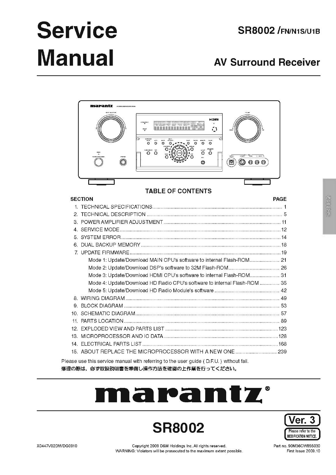
Marantz SR 8002 Service Manual

This is the 203 pages manual for Marantz SR 8002 Service Manual.
Read or download the pdf for free. If you want to contribute, please mail your pdfs to info@audioservicemanuals.com.

Page: 1 / 203
left right
Marantz SR 8002 Service Manual

Extracted text from Marantz SR 8002 Service Manual (Ocr-read)


Page 1

Service
Manual

SR8002 lFN/N1SIU1B

AV Surround Receiver

k-L u w-

kg 55
ET

TABLEOFCONTENTS

SECTION PAGE
1. TECHNICAL SPECIFICATIONS ............................................................................................ 1
2. TECHNICAL DESCRIPTION ................................................................................................ 5
3. POWER AMPLIFIER ADJUSTMENT ................................................................................... 11
4. SERVICE MODE .................................................................................................................. 12
5. SYSTEM ERROR ................................................................................................................. 14
6. DUAL BACKUP MEMORY ................................................................................................... 18
7. UPDATE FIRMWARE ........................................................................................................... 19
Mode 1: Update/Download MAIN CPU's software to internal Flash-ROM ..................... 21

Mode 2: Update/Download DSP's software to 32M Flash-ROM .................................... 26

Mode 3: Update/Download HDMI CPU's software to internal Flash-ROM ..................... 81

Mode 4: Update/Download HD Radio CPU's software to internal Flash-ROM .............. 35

Mode 5: Update/Download HD Radio Module's software .............................................. 42

8. WIRING DIAGRAM ....................................................................................................... 49
9. BLOCK DIAGRAM .............................................................................................................. 53
10. SCHEMATIC DIAGRAM ...................................................................................................... 57
11. PARTS LOCATION .............................................................................................................. 89
12. EXPLODED VIEW AND PARTS LIST ................................................................................ 123
13. MICROPROCESSOR AND IC DATA ........................................................................... 128
14. ELECTRICAL PARTS LIST ................................................................................................ 168
15. ABOUT REPLACE THE MICROPROCESSOR WITH A NEW ONE ............................. 239

Please use this service manual with referring to the user guide ( D.F.U. ) without fail.
games.wammaaeagfiosmasaaamx¢¥afiat

ma la Ill 1 ®
SR8002 31:21.3:

MODIFICATION NOTICE.

UI

X0447V02DMIDG0910 Copyright 2009 D&M Holdings |nc.A|| rights reserved. Part no. 90M36CW855030
WARNING: Violators will be prosecuted to the maximum extent possible. First Issue 2009.10

Page 2

MARANTZ DESIGN AND SERVICE

Using superior design and selected high grade components, MARANTZ company has created the ultimate in stereo sound.
Only original MARANTZ parts can insure that your MARANTZ product will continue to perform to the specifications for which
it is famous.

Parts for your MARANTZ equipment are generally available to our National Marantz Subsidiary orAgent.

ORDERING PARTS :

Parts can be ordered either by mail or by Fax.. In both cases, the correct part number has to be specified.

The following information must be supplied to eliminate delays in processing your order:

1. Complete address

2. Complete part numbers and quantities required

3. Description of parts

4. Model number for which part is required

5. Way of shipment

6. Signature : any order form or Fax. must be signed, otherwise such part order will be considered as null and void.

- USA - - EUROPE 1' TRADING - * CANADA-
MARANTZ AMERICA, INC MARANTZ EUROPE B.V. D&M CANADA INC.
100 CORPORATE DRIVE P. O. BOX 8744, BUILDING SILVERPOINT 57505 APPLE CREEK BLVD,
MAHWAH, NEW JERSEY 07430 BEEMDSTRAAT11, 5653 MA EINDHOVEN MARKHAM, ONTARIO L3R 581
USA THE NETHERLANDS CANADA
PHONE : +31 ,40 , 2507844
FAX : +31 , 40 72507860

JAPAN i KOREA -
D&M Holdings Inc. fiftfifi 5:4 _7y PINK-1154 ya; D&M SALES AND MARKETING KOREA LTD.
D&M BUILDING, 2-1 NISSHlN-CHO, CHUNG JIN BID.,#1001,

KAWASAKI-KU, KAWASAKI-SHI, 5375, WONHYO RC) 3 GA, YONGSANEGU,
KANAGAWA, 210-8569 JAPAN ll: ti Tatow SEOUL, 1407719, KOREA
fifilllfidllfifilllfiEEiEm-I D&ML:'J|J PHONE : +82 , 2 , 323 , 2155
FAX . +82 -2 - 323 -2154

- CHINA

MARANTZ SHANGHAI TRADING LTD.
ROOM506 SHANGHAI LIGHT INDUSTRY MANSION
1578 NANJING (WEST) ROAD SHANGHAI
CHINA

TEL ' 021 , 6248 , 1064

FAX ' 021 s 6248 , 3565

NOTE ON SAFETY :

Symbol A Fire or electrical shock hazard. Only original parts should be used to replaced any part marked with symbol A .
Any other component substitution (other than original type), may increase risk of fire or electrical shock hazard.

fifiidfiifi :
AleUCU/égflfilat. asiiaaewaca. rJZWtEEéILTUéEB&$%®E®7EIfiHL/TFémo

SHOCK, FIRE HAZARD SERVICE TEST :

CAUTION : After servicing this appliance and prior to returning to customer, measure the resistance between either primary AC
cord connector pins ( with unit NOT connected to AC mains and its Power switch ON ), and the face or Front Panel of product
and controls and chassis bottom.

Any resistance measurement less than t Megohms should cause unit to be repaired or corrected before AC power is applied,
and verified before it is return to the user/customer.

Ref. UL Standard No. 1492.

In case of difficulties, do not hesitate to contact the Technical
Department at above mentioned address.

070719MZ