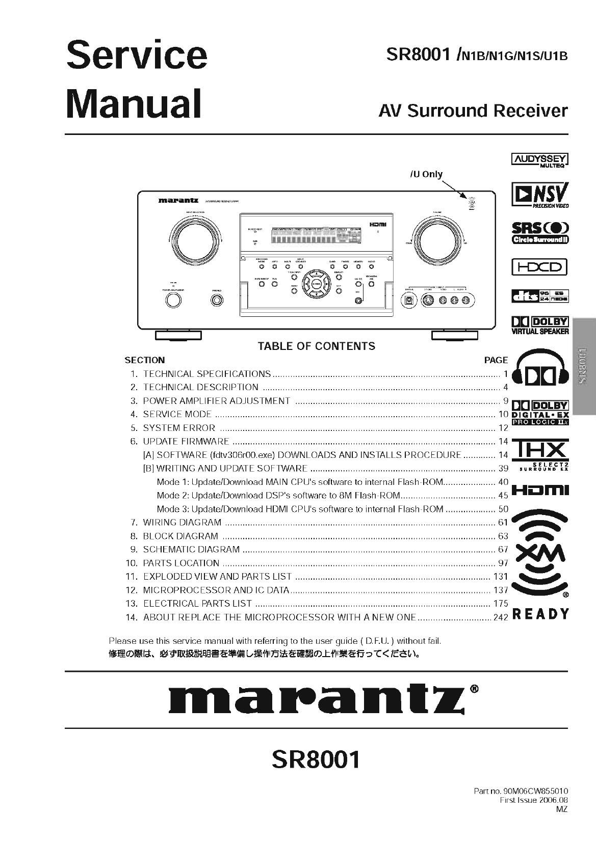
Marantz SR 8001 Service Manual

This is the 132 pages manual for Marantz SR 8001 Service Manual.
Read or download the pdf for free. If you want to contribute, please mail your pdfs to info@audioservicemanuals.com.

Page: 1 / 132
left right
Marantz SR 8001 Service Manual

Extracted text from Marantz SR 8001 Service Manual (Ocr-read)


Page 1

serVi ce SR8001 IN1BIN1GIN1SIU1B
Ma I1 U a I AV Surround Receiver


AUDYSSEY
MULTEO
IU Only
2.43%
W W; 535(0)
Ifllllllllllll....ra&a M
Q I-DCD
; i 1 9-6 3
C) l 24
- FEM-Em
E H
TABLE OF CONTENTS
SECTION PAGE
I. TECHNICAL SPECIFICATIONS ........................................................................................... 1 DD
2. TECHNICAL DESCRIPTION ............................................................................................... 4
3. POWER AMPLIFIER ADJUSTMENT .................................................................................. 9 DD DDLBY
4. SERVICE MODE ................................................................................................................ IOnIeIuL-Ex
5. SYSTEM ERROR ........................................................................................................ 12 PRO LOG: '1
6. UPDATE FIRMWARE ......................................................................................................... I4 1-
[A] SOFTWARE (fdtv306r00.exe) DOWNLOADS AND INSTALLS PROCEDURE ............. I4 HX
[B] WRITING AND UPDATE SOFTWARE .......................................................................... 39 unfit-5.5L?
Mode 1: Update/Download MAIN CPU' s software to internal Flash ROM ..................... 40
Mode 2: Update/Download DSP' S software to 8M Flash- ROM ...................................... 45 Hnml
Mode 3: Update/Download HDMI CPU' S software to internal FlashFROM .................... 50 61A
7. WIRING DIAGRAM ............................................................................................................ A
8. BLOCK DIAGRAM ............................................................................................................. 63 A
9. SCHEMATIC DIAGRAM ..................................................................................................... 67 m
10. PARTS LOCATION ....................................................................................................... 97 v
II. EXPLODED VIEW AND PARTS LIST .............................................................................. 131 V
12. MICROPROCESSORANDIC DATA ................................................................................ 137%
13. ELECTRICAL PARTS LIST .............................................................................................. 175
I4. ABOUT REPLACE THE MICROPROCESSOR WITH A NEW ONE ............................. 242 R E A D Y
Please use this service manual with referring to the user guide ( D. F.U. ) Without fail.
Isflafltah Ma'flllfiERHEEE-filfi bifiiFEifiEfiE%®JflF¥Efi-fc<fiam.
m a ra n I 1 ®
Part no. 90M06CW855010

First Issue 2006.08
MZ

Mme]

Page 2

MARANTZ DESIGN AND SERVICE

Using superior design and selected high grade components, MARANTZ company has created the ultimate in stereo sound.
Only original MARANTZ parts can insure that your MARANTZ product will continue to perform to the specifications for which

it is famous.

Parts for your MARANTZ equipment are generally available to our National Marantz Subsidiary or Agent.

ORDERING PARTS :

Parts can be ordered either by mail or by FaX.. In both cases, the correct part number has to be specified.
The following information must be supplied to eliminate delays in processing your order:

I. Complete address

2. Complete part numbers and quantities required

3. Description Of parts

4. Model number for which part is required

5.Way Of shipment

6. Signature : any order form or Fax. must be Signed, otherwise such part order will be considered as null and void.

- USA - EUROPE [TRADING - m CANADA-
MARANTz AMERICA, INC MARANTZ EUROPE B.V. MARANTZ CANADA INC.
100 CORPORATE DRIVE P. 0. BOX 8744, BUILDING SILVERPOINT 5,505 APPLE CREEK BLVD.
IVIAHWAH, NEW JERSEY 07430 BEEMDSTRAAT11. 5653 MA EINDHOVEN MARKHAM, ONTARIO L3R 581
USA THE NETHERLANDS CANADA
PHONE:+31+40+2507844 PHONE:905-415-9292
FAX : +31 , 40 , 2507860 FAX : 905 , 475 , 4159
* AUSTRALIA- * THAILAND - * SINGAPORE -
QualiFi Pty Ltd. MRZ STANDARD C0., LTD wo KEE HONG DISTRIBUTION PTE LTD
24 LIONEL ROAD, 745 . 754 MAHACHAI ROAD No.1 JALAN KILANG TIMOR
MT. WAVERLEY VIC 3149 WANGBURAPAPIROIVI, PHRANAKORN, #08-03 PACIFIC TECH CENTRE
AUSTRALIA BANGKOK, 10200 THAILAND SINGAPORE 159303
PHONE : +61 . (0)37954371522 PHONE:+66+2+222 9181 PHONE:+65 6376 0338
FAX : +61 , (0)3 , 9543 , 3677 FAX : +66 , 2 , 224 6795 FAX : +65 6376 0166
7 NEW ZEALAND - * TAIWAN - i MALAYSIA -
WILDASH AUDIO SYSTEMS Nz PAI- YUING C0.. LTD. W0 KEE HONG ELECTRONICS SDN. BHD.
14 MALVERN ROAD MT ALBERT 6 TH FL NO, 148 SUNG KIANG ROAD, 2ND FLOOR BANGUNAN INFINITE CENTRE
AUCKLAND NEW ZEALAND TAIPEI, 10429, TAIWAN R.O.C. LOT 1, JALAN 1376, 46200 PETALING JAYA
PHONE : +64 , 9 , 8451958 PHONE: +886 - 2 - 25221304 SELANGOR DARUL EHSAN, MALAYSIA
FAX ; +64 , 9 , 8463554 FAX : +886 . 2 . 25630415 PHONE : +60 . 3 .7954 8088
FAX : +60 . 3 . 7954 7088
T JAPAN 7 KOREA -
D&M Holdings Inc. Hag; $4 _7y FIAm-Jb?4 ygz MARANTZ KOREA co., LTD.
D&M BUILDING, 2+1 NISSHINPCHO, ROOM 604, ELECTRO OFFICE, 1658,
KAWASAKIKU, KAWASAKIPSHI, HANGGANGVRO 3GA, YONGSANVKU,
KANAGAWA, 21078569 JAPAN A; #i T210455!) SEOUL, 140.013, KOREA
##dllfilllflfijrfillllfizafiflmd D&M|:JIJ PHONE : +82 . 2 . 323 . 2155
FAX :+82 2 323 , 2154

- CHINA

MARANTZ SHANGHAI TRADING LTD.
ROOMBOE SHANGHAI LIGHT INDUSTRY MANSION
1578 NANJING (WES'D ROAD SHANGHAI
CHINA

TEL : 021 - 6248 -1064

FAX : 021 - 6248 - 3565

SHOCK, FIRE HAZARD SERVICE TEST :
CAUTION : After servicing this appliance and prior to returning to customer, measure the resistance between either primary AC
cord connector pins ( with unit NOT connected to AC mains and its Power switch ON ), and the face or Front Panel of product and

controls and chassis bottom.

Any resistance measurement less than 1 lVlegohms should cause unit to be repaired or corrected before AC power is applied, and
verified before it Is return to the user/customer.

Ref. UL Standard No. 1492.

In case Of difficulties. do not hesitate to contact the Technical

Department at above mentioned address.

060607MZ

Page 118

IC41 :CS4382A-CQ

Pin Name # Pin Description

MUTEC1 41 Mute Control (Output) - The Ivlute Control pins go high during power-up initialization, reset, muting,

MUTEC234 22 power-down or ifthe master clock to le It/nght clock frequency ratio is incorrect These pins are intended
to be used as a control for external mute Circmts to preventthe clicks and pops that can occurin any Sin-
gle supply system The use of external mute circuits are not mandatory but may be desired for designs
requiring the absolute minimum in extraneous clicks and pops

AOUTA1 +,- 39, 4O Differential Analog Output (Output) - The full scale differential analog output level is specified in the

AOUTB1 +,- 38, 37 Analog Characteristics specification table

AOUTA2 +,- 35, 36

AOUTB2 +,- 34, 33

AOUTA3 +,- 29. 30

AOUTB3 +,- 28, 27

AOUTA4 +,- 25. 26

AOUTBA +,- 24, 23

VA 32 Analog Power (Input) -Positive power supply forthe analog section Referto the Recommended Oper-
ating Conditions for appropriate voltages

VLS 43 Serial Audio Interface Power (Input) - Deterrnines the required signal level forthe serial audio inter-

face Referto the Recommended Operating Conditions for appropriate voltages

Control Port Definitions

SCLICCLK )5 Serial Control Port Clock (Input)- Serial clock forthe serial control port Requires an external pull-up
resistorto the logic interface voltage in I2C mode as shown in the Typical Connection Diagram

SDAICDIN l6 Serial Control Data(/nput/Output) - SDA is a data l/O line in |2C mode and reqUIres an external pull-up
resistorto the logic interface voltage, as shown in the Typical Connection Diagram CDIN is the input
data line forthe control port interface in SRI mode

ADO/CS 17 fldress Bit 0 (IZC)IControl Port Chip Select (SPI) (/nput) - ADO is a chip address pin in I2C mode,-

CS is the chip select signal for SPI format

Stand-Alone Definitions

M0
M1
M2
M3

l7
l6
l5
42

Mode Selection (Input)- Determines the operational mode ofthe deVIce as detailed in Tables 6 and 7

DSD Definitions

DSD_SCLK 42 DSD Serial Clock (/nput) - Serial clock forthe Direct Stream Digital audio interface

DSD_EN 7 DSD-Enable (Input)-When held at logic '1' the deVIce Will enter DSD mode (Stand-Alone mode only)
DSDA1 3 Direct Stream Digital Input (/nput)- Input for Direct aream Digital serial audio data

DSDB1 2

DSDA2 1

DSDBZ 48

DSDA3 47

DSDBs 46

DSDA4 45

DSDBA 44

IC61 :NJM2235MTE1

lNlA GNDI

INZB V CTLZ INZA ENDS INJD

[.e|

is]

I ini lifl ni m m

L Bias Type

A

HL

O
Clamp Type [ Clamp Type H

o
\r
0

ll

r--

_i_llfll;l|:ijul

[NIB CTL)

DUTl GN02 0UT2 0UT3 CT LS INZA

NJMTZBSD
"JIM? SM

160