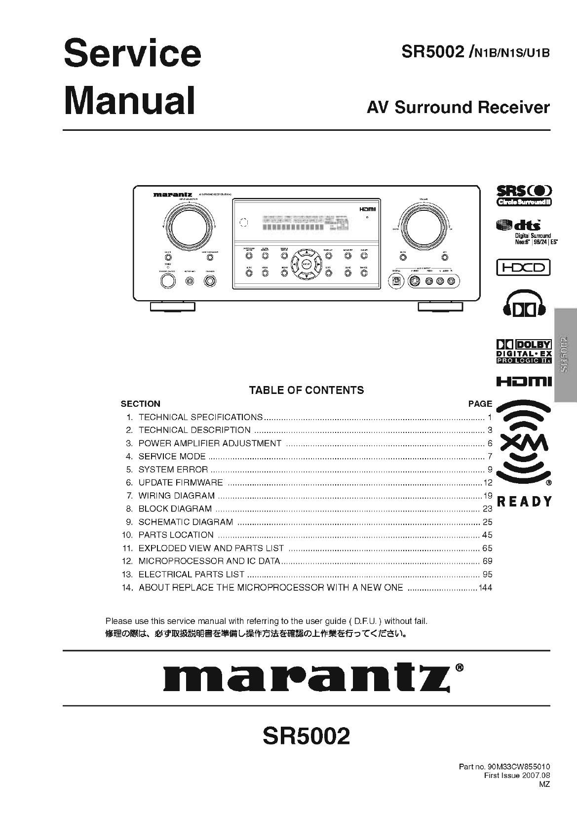
Marantz SR 5002 Service Manual

This is the 122 pages manual for Marantz SR 5002 Service Manual.
Read or download the pdf for free. If you want to contribute, please mail your pdfs to info@audioservicemanuals.com.

Page: 1 / 122
left right
Marantz SR 5002 Service Manual

Extracted text from Marantz SR 5002 Service Manual (Ocr-read)


Page 1

serVice SR5002 lN1B/N1S/U1B
Man ual AV Surround Receiver

SBSC.)
:1 I» . @dts
Digital Surround
m m M Namb'HiSIZAIES'
5 5 5 65> "5 '5" 5
5 5 $5385 5 5 "DCD
6:}.
mm

DIGITAL-EX

HDI'I'II

3.: 151m.

TABLE OF CONTENTS

SECTION PAGE A

1. TECHNICAL SPECIFICATIONS ........................................................................................... 1 A
2. TECHNICAL DESCRIPTION ............................................................................................... 3 A

3. POWER AMPLIFIER ADJUSTMENT .................................................................................. 6 m
4. SERVICE MODE .................................................................................................................. 7 v

5. SYSTEM ERROR ................................................................................................................. 9 V
6. UPDATE FIRMWARE ......................................................................................................... 12 VS
7. WIRING DIAGRAM ............................................................................................................. 19

9. BLOCK DIAGRAM ............................................................................................................. 23R E A D Y
9. SCHEMATIC DIAGRAM .................................................................................................... 25
1o. PARTS LOCATION ............................................................................................................ 45

11. EXPLODED VIEW AND PARTS LIST ............................................................................... 65
12. MICROPROCESSOR AND IC DATA .................................................................................. e9
13. ELECTRICAL PARTS LIST ................................................................................................ 95
14. ABOUT REPLACE THE MICROPROCESSOR WITH A NEW ONE ............................. 144

Please use this service manual with referring to the user guide ( D.F.U. ) Without fail.
igiimfiiat. 1%?ElifigfiflflgéfiifibfiiFE?fiEfiE$®LiF¥ET:-DC< EEM.

man-anti

SR5002

Part no. 90M330W855010
First Issue 2007.08
MZ

Page 2

MARANTZ DESIGN AND SERVICE

Using superior design and selected high grade components, MARAN'IZ company has created the ultimate in stereo sound.
Only original MARAN'IZ parts can insure that your MARAN'IZ product will continue to perform to the specifications for which
it is famous.

Parts for your MARAN'IZ equipment are generally available to our National Marantz Subsidiary or Agent.

ORDERING PARTS :

Parts can be ordered either by mail or by Fax.. In both cases, the correct part number has to be specified.

The following information must be supplied to eliminate delays in processing your order:

1. Complete address

2. Complete part numbers and quantities required

3. Description of parts

4. Model number for which part is required

5. Way of shipment

6. Signature : any order form or Fax. must be signed, otherwise such part order will be considered as null and void.

- USA - - EUROPEITRADING - * CANADA-
MARANTZ AMERICA, INC MARANTZ EUROPE B.V. D&M CANADA INC.
100 CORPORATE DRIVE P. 0. BOX 8744, BUILDING SILVERPOINT 57505 APPLE CREEK BLVD,
MAHWAH, NEW JERSEY 07430 BEEMDSTRAAT11, 5653 MA EINDHOVEN MARKHAM, ONTARIO L3R 581
USA THE NETHERLANDS CANADA
PHONE : +31 7 40 7 2507844
FAX : +31 7 40 7 2507860

* JAPAN , KOREA -
D&M Holdings Inc. W $4 -7y FILxflt-Jb?4 V07 D&M SALES AND MARKETING KOREA LTD.
D&M BUILDING, 2-1 NISSHlN-CHO, CHUNG JIN B/D.,#1001,

KAWASAKI-KU, KAWASAKI-SHI, 5375, WONHYORO 3 GA, YONGSAN7GU,
KANAGAWA, 21078569 JAPAN iii 4i F21o~asas SEOUL, 1407719, KOREA
#filllfillllfifiillllfilzaiéflflzd omen: PHONE : +82 , 2 , 323 72155
FAX .+82-2-323 -2154

- CHINA

MARANTZ SHANGHAI TRADING LTD.
ROOM506 SHANGHAI LIGHT INDUSTRY MANSION
1578 NANJING (WEST) ROAD SHANGHAI
CHINA

TEL :021 7 6248 7 1064

FAX '021 7 6248 7 3565

NOTE ON SAFETY :

Symbol A Fire or electrical shock hazard. Only original parts should be used to replaced any part marked with symbol A.
Any other component substitution (other than original type), may increase risk of fire or electrical shock hazard.

fifiidfiig 3
Amowasnusia asisessfluscm £~ft§fiéflfm-§flfl$%®-®firl§fifi L/TFémo

SHOCK, FIRE HAZARD SERVICE TEST :

CAUTION : After servicing this appliance and prior to returning to customer, measure the resistance between either primary AC
cord connector pins ( with unit NOT connected to AC mains and its Power switch ON ), and the face or Front Panel of product
and controls and chassis bottom.

Any resistance measurement less than t Megohms should cause unit to be repaired or corrected before AC power is applied,
and verified before it is return to the user/customer.

Fief. UL Standard No. 1492.

In case of difficulties, do not hesitate to contact the Technical
Department at above mentioned address.

07071 QMZ

Page 56

IC29 : CS42528-CQ
-

2. PIN DESCRIPTIONS

n S
2 2 if E 5 3 8
D 0 F (V D
m. 8| a TI él 5 g g ml 5 TI (/7 g D- E
>< X X < 2: E D D >< E <( 4 o o >< ><
L) (J U U) U1 0 <3: c: L) Di (D > D > k II
l_l l_l l_l l_l l_l l_l l_l l_l l_l l_l l_l l_l l_l l_l l_l l_l
64 e3 s2 61 so 59 58 57 5s 55 54 53 52 51 5o 49
CXESDINI E1 4sjaxp1rcpo1
CXESCLK E 2 47 ijp2rePo2
CX_LRCK E 3 4e jRXPSIGPO3
VD E 4 45 ijp4rcpo4
DGND E 5 44 ijp5reP05
\ILC E e 43 jRXPBIGPOB
scuccm E 7 42 ijprrcPor
SDAICDOUT E 8 CS42528 41 ] VARx
ADIICDIN E 9 4o jAeND
ADOIEE 1o 39 jiprir
lNT E11 38 jmurEc
WE12 37 jAOUTM-
AINFLEIS 35 jAourA1+
AINR+EI4 351Aours1+
AINL+ E15 34 jAOUTBi-
AWL E 16 33 Mourns
1? 1819 20 2122 23 24 25 26 27 28 29 30 3132
(j + Q (if + + gr <( Q (J) + + (4) (41 + +
> I: Z en V q <( > Z to m m s: m N N
25225522
c: 2 2 2 2 2 2 2 2 2 2 2
Pin Name # Pin Description
CX_SDIN1 1 Codec Serial Audio Data Input (Input) - Input for twos complement serial audio data.
CX_SDIN2 64
CX_SDIN3 63
CX_SDIN4 62
CX_SCLK 2 CODEC Serial Clock (Input/Output) - Serial clock forthe CODEC serial audio interface.
CX_LRCK 3 CODEC Left Right Clock (Input/Output) - Determines which channel, Left or Right, is currently active on
the CODEC serial audio data line.
VD 4 Digital Power (Input) - Positive power supply for the digital section.
51
DGND 5 Digital Ground (Input) - Ground reference. Should be connected to digital ground.
52
VLC 6 Control Port Power (Input) - Determines the required signal level for the control port.

SCLICCLK 7 Serial Control Port Clock (Input) - Serial clock for the serial control port. Requires an external pull-up
resistorto the logic interface voltage in IZC mode as shown in the Typical Connection Diagram.

SDAICDOUT 8 Serial Control Data (Input/Output) - SDA is a data IIO line in IZC mode and requires an external pull-up
resistorto the logic interface voltage, as shown in the Typical Connection Diagram. CDOUT is the output
data line forthe control port interface in SPI mode.

AD1ICD|N 9 Address Bit 1 (IZC)ISerial Control Data (SPI) (Input) - AD1 is a chip address pin in IZC mode; CDIN is
the input data line for the control port interface in SPI mode.

78