Marantz SR 2000 L Owners Manual

This is the 11 pages manual for Marantz SR 2000 L Owners Manual.
Read or download the pdf for free. If you want to contribute, please mail your pdfs to info@audioservicemanuals.com.

Page: 1 / 11
left right
Marantz SR 2000 L Owners Manual

Extracted text from Marantz SR 2000 L Owners Manual (Ocr-read)


Page 1

Printed in Japan

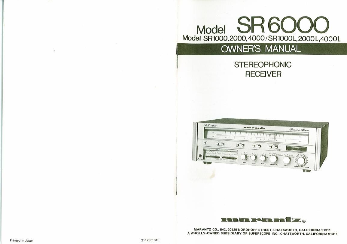
Model SR 6000

Model §R0992000,4000/SR1000L,2000L,4000L
OWNERS MANUAL

STEREOPHONIC
RECEIVER

maranlzga

MARANTZ 00., INC. 20525 NORDHOFF STREET, CHATSWORTH, CALIFORNIA 91311
A WHOLLY-OWNED SUBSIDIARY OF SUPERSCOPE INC., CHATSWORTH. CALIFORNIA 91311

2112851310

Page 2

sn 1000/2000/1000L/2000l
@ ©

1®3®© 8

SR 4000/4000L/6000

Figure 1. Rear Panel Connection Facilities
Figure 1. Raccordements a la lace arriere
Abbildung 1. Riickseitige Anschliisse und Verbindungen

FOREWORD

To obtain maximum nerformance and
enjoyment from the Stereo Receiver, please
study these instructions carefully, Do not
plug in or connect this receiver until you
have read and complied with this handbook
of instructions.

This is a universal handbook designed to
provide instructions in English, French and
German for all Marantz products sold world-
wide.

This manual is divided into two parts. The
first covers installation and operation in
simple, non-technical language. The second
describes your model in more detail with
functional explanations.

For quick identification of the controls and
connections. references to them are printed
in BOLDFACE type, exactly as they appear
on the front and rear panels of your
receiver.

Your Marantz product has been specially
prepared to comply with the household
power and safety requirements that exist
in your locale. Please check the alphabeti»
cal suffix following the serial number of
your Marantz product. Refer to the follow-
ing table to note the differences that exist
between your unit and the unit pictured
and described in this manual.

C » Operating Voltage: lZOVAC
Unit cannot be converted to
operated on the other voltages.

N »The unit is set for operation on
ZZOVAC.
The external voltage selector on
the rear panel allows to set the
unit for operation on 110»120/
220240 V AC. There is an ex-
ternal fuse on the rear panel. There
are no AC convenience outlets on
the rear panel.
A ground post is provided for
connection to a bonified earth
ground.

P , Operating Voltage: 120 V AC

Should it become necessary to convert
this unit to a different operating voltage,
please note that a proper fuse must be
substituted for the one currently in the
unlt.

FOR UNITS SOLD IN THE UNITED
KINGDOM:

(91

IMPORTANT

The wires in this mains lead are coloured in
accordance with the following code.

0 8....

Blue - Neutral
Brown _ Live

As the colours of the wires may not corres-

pond with the terminal identification in

your plug, proceed as follows:

tr Connect brown wire to the terminal
marked "L or coloured brown or red,

* Connect blue wire to the terminal marked
"N or coloured blue or black.

For i3 A plugs, conforming to BS 1363, use
a 3 A fuse.
For other plugs, use a 5 A or lower fuse in

the plug or adaptor or at the distribution
board.