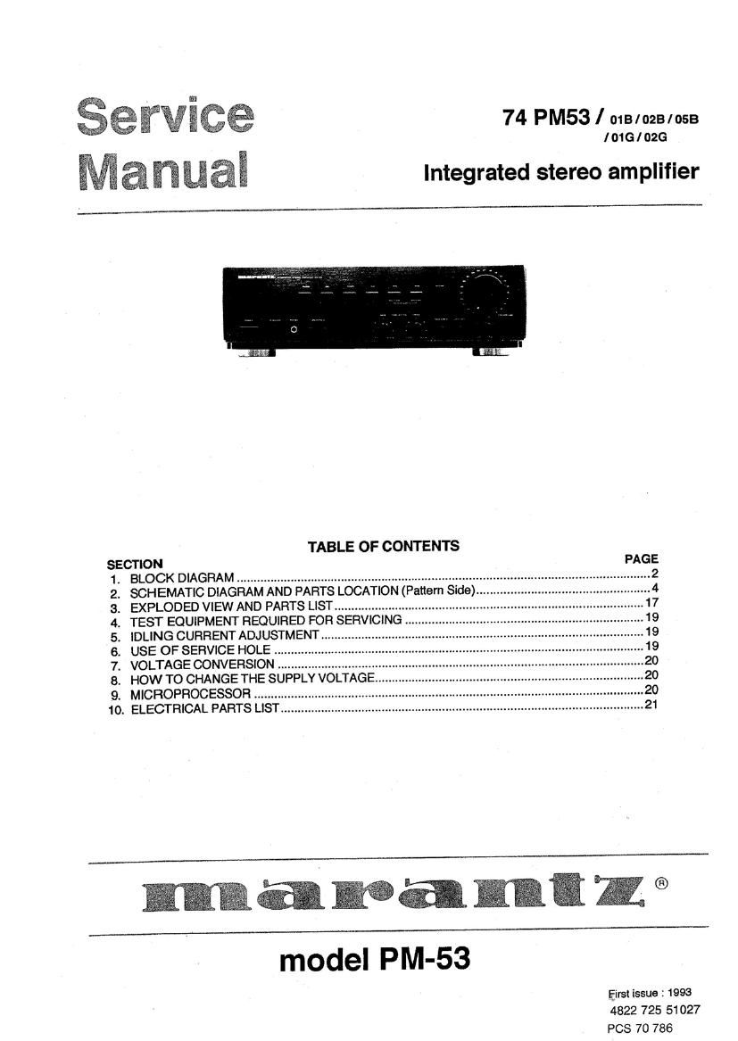
Marantz PM 53 Service Manual

This is the 18 pages manual for Marantz PM 53 Service Manual.
Read or download the pdf for free. If you want to contribute, please mail your pdfs to info@audioservicemanuals.com.

Page: 1 / 18
left right
Marantz PM 53 Service Manual

Extracted text from Marantz PM 53 Service Manual (Ocr-read)


Page 1

74 PM53 / nus/0231053

IOIGIOZG

Integrated stereo amplifier

TABLE OF CONTENTS


SECTION
BLOCK DIAGRAM ..............................
SCHEMATIC DIAGRAM AND PARTS
EXPLODED VIEW AND PARTS LIST ...........................
TEST EQUIPMENT REQUIRED FOR SERVICING ..
IDLING CURRENT ADJUSTMENT .....
USE OF SERVICE HOLE
VOLTAGE CONVERSION .......
HOW TO CHANGE THE SUPP
. MICROPROCESSOR ..............
10 ELECTRICAL PARTS LIST_.....

PNPVFSN.

model PM-53

Eirst issue: 1993
4822 725 51027
PCS 70 786

Page 2

TECHNICAL SPECIFICATIONS ( DIN )

Power output
RMS 8 Ohms (20 Hz - 20 kHz)
Din 8 Ohms /4 Ohms .....

lHF dynamic power
8 Ohms /4 Ohms ...........................
THD at 8 Ohms HMS rated output.
lntermodulation distortion
Dampingfactor


Magnetic cartridge input

Input sensitivityimpedance
Accuracy of trequency response to RIAA
Signal to noise ratio

Tuner / CD/ Aux/ Tape inputs
input sensitivity impedance
Signal to noise ratio
Frequency response (- )
Tone characteristic (100 Hz and 10 kHz)
Channel separation ................................

150 mV [33 k ohms
..... 103 dB
0 -70 kHz
..i:6dB
.> 85 dB

General
Power Requirements
I018 /01G version (4 voltages) 110 I 120 /220 I240 V AC, 50/60 Hz
IOZB / 026 version .................... 230 V AC 50 Hz
IOSB verSIon ...24OVAC50Hz
Dimensions
Panel width "420 mm
Panel Height. 118mm
Depth ....300 mm
Weight
Unit alone 63 kg

Specifications subject to change without prior notice.

1 . BLOCK DIAGRM

E0 AMP

PHONO @-

-l RlAA:

RC-S
lN/OUT

i?


INPUT
SELECTOR .
REC OUT 1.
SELECTOR
LC7822 BALANCE § MAS
LOOONESS
MOTOR DRIV. -w;{:
U-COM '
KEY SW. I:
2