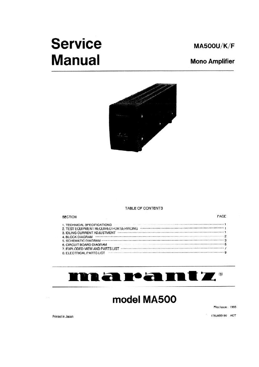
Marantz MA 500U K F Owners Manual

This is the 12 pages manual for Marantz MA 500U K F Owners Manual.
Read or download the pdf for free. If you want to contribute, please mail your pdfs to info@audioservicemanuals.com.

Page: 1 / 12
left right
Marantz MA 500U K F Owners Manual

Extracted text from Marantz MA 500U K F Owners Manual (Ocr-read)


Page 1

Service MA500U/K/F
M a n u a I Mono Amplifier

TABLE OF CONTENTS

SECTION PAGE
1. TECHNICAL SPECIFICATIONS

2 TESI EOUIPMtNI REQUIRED FOR SERVICING '
3. IDLING CURRENTADJUSTMENT ~

4, BLOCK DIAGRAM
5 SCHFMATIC DIAGRAM
6. CIRCUIT BOARD DIAGRAM
7. EXPLODED VIEW AND PARTS LIST -
8. ELECTRICAL PARTS LIST


wmum4-Id

maranll®

model MA500

Firsi issue. 1993

Primed In Japan 176J655190 ACT

Page 2

MAFIANTZ DESIGN AND SERVICE

Using superior design and selected high grade
components, MARANTZ company has mated the
ultimate in stereo sound.

Only orlpinll MARANTZ parts can insure that your
MARANTZ product will continue to perform to the
specifications for which it is famous.

Parts {or your MARANTZ equipment are generally
available to our National Marantz Subsidiary or Agent.

ORDERING PARTS:

Parts can be ordered either by mail or by talex. In both

cases. correct part number has to be specified.

The following information must be supplied to eliminate

delays in processing your order:

1. Complete address

2. Complete part numbers and quantities required

3. Description of parts

4. Model number for which part is required

5. Way of shipment

6. Signature: any order form or telex must be signed
otherwise such part order will be considered as null
and void.

MARANTZ EUROPE B.V.

Vestdijk 9

5600 MD Eindhoven

The Netherlands

Phone : +31-40v758290

Fax : +31-40-758299

Telex : 35000 PHTC NL routing ind.

MARANI'Z USA

1150 FEEHANVILLE DR.

MOUNT PROSPECT, ILLNOIS 60056
USA

PHONE: 8006646633

FAX: 708-299-4005

7 .. AH:
'3in . 7 / /fiiifi:a

* H: T! #HHMNWTMIXH7TE35IIV
fit$fl $150 Xfiflmfizfilfimlr5u9g

SHOCK, FIRE HAZARD SERVICE TEST:

CAUTION: Atter servicing this appliance and prior to
returning to customer, measure the resistance between
either primary AC cord connector pins (with unit NOT
connected to AC mains and its Power switch 0N), and the
face or Front Panel of product and controls and chassis
bottom.

Any resistance measurement less than 1 Megohms should
cause unit to be reparied or corrected before AC power is
applied, and verified before return to user/customer,

Ref. UL Standard No. 1270. Para 74. 3. D (Mandatory
Test alter servicing Electrical Appliances, effective
7-1-83).

In case of difficulties, do not hesitate to contact the Technical
Department at abovelnentiuned address.