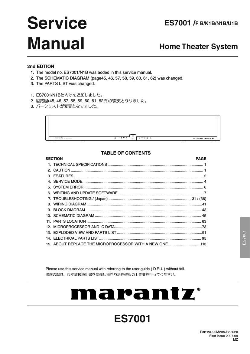
Marantz ES 7001 Service Manual

This is the 98 pages manual for Marantz ES 7001 Service Manual.
Read or download the pdf for free. If you want to contribute, please mail your pdfs to info@audioservicemanuals.com.

Page: 1 / 98
left right
Marantz ES 7001 Service Manual

Extracted text from Marantz ES 7001 Service Manual (Ocr-read)


Page 1

se rv i ce E37001 IF B/K1B/N1B/U1B
Manual Home Theater S stem
Y

2nd EDTION
1. The model no. ES7001/N1 B was added in this service manual.
2. The SCHEMATIC DIAGRAM (page45, 46, 57, 58, 59, 60, 61, 62) was changed.
3. The PARTS LIST was changed.

1. ES7001/NiBiiiD1IVEiEIJUlJi Uta
2. @IPEIMS, 46, 57, 58, 59, 60, 61, 62E)b§§t-U a? [27:0
3. /\°-J U R Lflgittflj % L/to

mm 0"111'? '-.| H 0"0

TABLE OF CONTENTS

SECTION
1. TECHNICAL SPECIFICATIONS..
CAUTION .....................................
FEATURES .........
SERVICE MODE.
SYSTEM ERROR ....................................
WRITING AND UPDATE SOFTWARE
TROUBLESHOOTING / (Japan) .
WIRING DIAGRAM ......................
BLOCK DIAGRAM ............
SCHEMATIC DIAGRAM
. PARTS LOCATION .............................
. MICROPROCESSOR AND IC DATA..
. EXPLODED VIEW AND PARTS LIST
ELECTRICAL PARTS LIST ................. ..
, ABOUT REPLACE THE MICROPROCESSOR WITH A NEW ONE ............................. 113


99°51???wa

_._._._._¢
ascends:

_
0!

Please use this service manual with referring to the user guide ( D.F.U. ) without fail.
iigiiwfifa-Ha. M?E¥}&E%EE§EEIE5 L2 §i$fi§£E6E3E®L1T¥Efi DT< 7335b In

marantz®

E37001

Part no. 90M20AJ855020
First Issue 2007.09
MZ

Page 2

MARANTZ DESIGN AND SERVICE

Using superior design and selected high grade components, MARANTZ company has created the ultimate in stereo sound.
Only original MARANTZ parts can insure that your MARANTZ product will continue to perform to the specifications for which
it is famous.

Parts for your MARANTZ equipment are generally available to our National Marantz Subsidiary or Agent.

ORDERING PARTS :

Parts can be ordered either by mail or by Fax.. In both cases, the correct part number has to be specified.

The following information must be supplied to eliminate delays in processing your order :

1. Complete address

2. Complete part numbers and quantities required

3. Description of parts

4. Model number for which part is required

5. Way of shipment

6. Signature : any order form or Fax. must be signed, othenIvise such part order will be considered as null and void.

- USA - - EUROPE/TRADING - 7 CANADA
MARANTZ AMERICA, INC MARANTZ EUROPE B.V. D&M CANADA INC.
100 CORPORATE DRIVE P. 0. BOX 8744, BUILDING SILVERF'OINT 5505 APPLE CREEK BLVD.
MAHWAH, NEW JERSEY 07430 BEEMDSTRAAT 11, 5653 MA EINDHOVEN MARKHAM, ONTARIO L3R 581
USA THE NETHERLANDS CANADA

PHONE : +31 - 40 - 2507844
FAX : +31 - 40 - 2507860

- JAPAN 7 KOREA
D&M Holdings Inc. fifigfi ?477/F1Am7iv?4 yfiz D&M SALES AND MARKETING KOREA LTD.
D&M BUILDING, 2-1 NISSHIN-CHO, CHUNG JIN B/D.,#1001,
KAWASAKI-KU, KAWASAKI-SHI, 7 53-5, WONHYOFIO 3 GA, YONGSAN-GU,
KANAGAWA, 210-8569 JAPAN 2:: 4: T210-3569 SEOUL, 140719, KOREA

75%;IIEIIIIU6WHIIEEBEHJJ24 D&MEJIJ PHONE : +82 - 2 - 323 - 2155
FAX : +82 , 2 - 323 - 2154

7 CHINA

MARANTZ SHANGHAI TRADING LTD.
ROOMSOG SHANGHAI LIGHT INDUSTRY MANSION
1578 NANJING (WEST) ROAD SHANGHAI
CHINA

TEL : 021 - 6248 - 1064

FAX : 021 - 6248 - 3565

NOTE ON SAFETY :
Symbol A Fire or electrical shock hazard. Only original parts should be used to replaced any part marked with symbol A .
Any other component substitution (other than original type), may increase risk of fire or electrical shock hazard.

fifiiafiifi :
ADVDU'CUSEBEDIJ. §§LE§HEBEDT6Q azia'IEEénruégrusssosmmra L'CTémo

SHOCK, FIRE HAZARD SERVICE TEST :

CAUTION : After servicing this appliance and prior to returning to customer, measure the resistance between either primary AC
cord connector pins ( with unit NOT connected to AC mains and its Power switch ON ), and the face or Front Panel of product
and controls and chassis bottom.

Any resistance measurement less than 1 Megohms should cause unit to be repaired or corrected before AC power is applied,
and verified before it is return to the user/customer.

Ref. UL Standard No. 60065.

In case of difficulties, do not hesitate to contact the Technical
Department at above mentioned address.

07071 9M2

Page 68

0501 : TA55508

TERMINAL

NAME

NO.

TYPE

5-V
TOLERANT

TERMINATION (2

DESCRIPTION

F'WM_P_3

45

DO

PWM 3 output difterential +)

FWM_P4

47

DO

PWM};

56

DO

(
PWM 4 output (difterential +)
PWM 5 output (difterential +)

PWMP_6

58

DO

PWM 6 output (diflerential +)

F'WM_P_7

50

DO

PWM 7 (lineout L) output (differential +)

FWM_Pv8

52

DO

PWM 8 (lineout R) output (difterential +)

RESERVED

21. 22,
23, 64

Connect to digital ground

RESET

11

DI

5V

Pullup

System reset input, activerlow. A system reset is generated by applying a logic
low to this terminal. RESET is an asynchronous control Signal that restores the
TASSSOB to its delault conditions, sets the valid output low, and places the
PWM in the hard mute (M) state. Master volume is immediately set to full
attenuation. On the release of RESET, if m is high, the system performs a 4.
to Sims device initialization and sets the volume at mute.

SCL

25

DI

5V

IZC serialrcontrol clock input/output

SCLK

27

DI

5V

Serial»audio data clock (shift clock) input

SDA

24

DIO

5V

I20 serialrcontrol datarinterface inputJoutput

SD|N1

31

BI

5V

F'ulldown

Serialraudio data input 1 is one of the serialrdata input ports. SDth supports
four discrete (stereo) data formats and is capable of inputting data at 64 Fs.

SD|N2

30

BI

5V

F'ulldown

Serialraudio data input 2 is one of the serialrdata input ports. SDINZ supports
four discrete (stereo) data formats and is capable of inputting data at 64 Fs.

SDINS

29

BI

5V

F'ulldown

Serialraudio data input 3 is one of the serialrdata input ports. SDINS supports
four discrete (stereo) data formats and is capable of inputting data at 64 Fs.

SD|N4

28

DI

5V

Fulldown

Serialraudio data input 4 is one of the serialrdata input ports. SD|N4 supports
four discrete (stereo) data formats and is capable of inputting data at 64 Fs.

VALID

39

DO

Output indicating validity of PWM outputs, activerhigh

VBGAP

10

Bandrgap voltage relerence. A pinout of the internally regulated 1.2VV reference.
Typically has a trnF lowiESR capacitor between VBGAP and AVSSJLL. This
terminal must not be used to power external devices.

VRiDlG

35

Voltage reference for 1.87V digital core supply. A pinout of the internally
regulated 1.87V power used by digital core logic. A 4.71LF lowiESR capacitorl3l
should be connected between this terminal and DVSS. This terminal must not
be used to power external devices.

VRiDF'LL

17

Voltage reference for 1.87V digital F'LL supply. A pinout of the internally
regulated 1.87V power used by digital PLL logic. A 0.111F lowiESR capacitorlal
should be connected between this terminal and DVSS_CORE. This terminal
must not be used to power external devices.

VRfiPWM

48

Voltage reference for 1.87V digital F'WM core supply. A pinout oi the internally
regulated 1.87V power used by digital PWM core logic. A 0.1rpF lowiESR
capacitorlal should be connected between this terminal and DvssfPWM. This
terminal must not be used to power external devices.

VRAiP LL

Voltage reference for 1.87V PLL analog supply. A pinout ol the internally
regulated 1.87V power used by PLL logic. A 0.11iF lowiESR capacitorl3) should
be connected between this terminal and AVSSJDLL. This terminal must not be
used to power external devices.

VRDiPLL

Voltage reference for 1.87V PLL digital supply. A pinout of the internally
regulated 1.87V power used by PLL logic. A 0.1rpF lowiESR capacitorl3) should
be connected between this terminal and AVSS_PLL. This terminal must not be
used to power external devices.

XTLilN

20

Al

XTLfiOUT and XTL__|N are the only LVCMOS terminals on the device. They
provide a reference clock for the TASSSOS via use of an external Iundamenr
talrmode crystal. XTL_IN is the 1er input port for the oscillator circuit. A
135MHz crystal (HCMAB) is recommended.

erfiour

19

AO

XTL_OUT and XTL_IN are the only LVCMOS terminals on the device. They
provide a reference clock for the TA85508 via use of an external tundamenr
talrmode crystal. XTL_OUT is the 1.87V output drive to the crystal. A 13.57MHZ
crystal (HCM49) is recommended.

(3) If desired, low-ESR capacitance values can be implemented by paralleling two or more ceramic capacitors of equal value. Paralleling
capacitors of equal value provides an extended high-frequency supply decoupling. This approach avoids the potential of producing
parallel resonance circuits that have been observed when paralleling capacitors of different values.

82