Marantz CD 400 Service Manual

This is the 29 pages manual for Marantz CD 400 Service Manual.
Read or download the pdf for free. If you want to contribute, please mail your pdfs to info@audioservicemanuals.com.

Page: 1 / 29
left right
Marantz CD 400 Service Manual

Extracted text from Marantz CD 400 Service Manual (Ocr-read)


Page 1

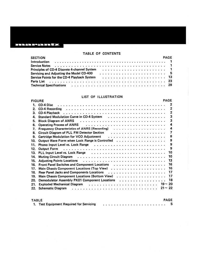
TABLE OF CONTENTS

SECTION PAG E
Introduction ............................................. 1
Service Notes ........................................ 1
Principles of 60-4 Discrete 4-channel System ....................... 1
Servicing and Adjusting the Model CD~400 . . . ......... . ........... 5
Service Points for the CD-4 Playback System . . . . . . . . . . . ............ 13
Parts List .......................................... 23
Technical Specifications .................................. 28

FIGURE PAGE
1 CD-4 Disc ................ . . . .................... 2
2CD-4Recording ................ ....... 2
3 CD4 Playback ............... . . .................. . . 2
4. Standard Modulation Curve in CD4 System ................. . . . . 3
5. Block Diagram of ANRS .......... . . . ................ . . 3
6 Operating Process of ANRS . . . . ........... . ..... . ....... 4
7 Frequency Characteristics of ANRS (Recording) ................... 4
8 Circuit Diagram of PLL FM Detector Section .................... 7
9. Cartridge Modulation for VCO Adjustment ..................... 8

10. Output Wave Form when Lock Range is Controlled .............. . . . . 9

11. Phone Input Level vs. Lock Range .......................... 9

12. Output Form ..................................... 9

13. PLL Input Level vs. Lock Range ........................... 10

14. Muting Circuit Diagram ................................ 10

15. Adjusting Points Locations .............................. 13

16. Front Panel Switches and Component Locations ................... 16

17. Main Chassis Component Locations (Top View) ....... . . . . . ........ 16

18. Rear Panel Jacks and Components Locations . . . . . ................ 17

19. Main Chassis Component Locations (Bottom View) .................. 17

20. Demodulator Assembly PK01 Component Locations ................. 18

21. Exploded Mechanical Diagram ......................... 19~ 20

22. Schematic Diagram ............................... 21 ~ 22

TABLE PAGE

1. Test Equipment Required for Servicing ....................... 5

Page 2

1. INTRODUCTION

This service manual was prepared for use by Authorized Warranty Stations and contains service
information for Marantz Model CD-400 CD»4 Demodulator.

Servicing information and voltage data included in this manual are intended for use by the
knowledgeable and experienced technician only. All instruction should be read carefully. No
attempt should be made to proceed without a good understanding of the operation in the
circuits.

The parts lists furnish information by which replacement part may be ordered from the
Marantz Company. A simple description is included for parts which can usually be obtained
through local suppliers.

2. SERVICE NOTES

The Model CD-4OO is a demodulator which reproduces discrete 4-channel sounds from CD-4
records. The CD-4OO is to be connected between a stereo record player provided with a CD-4
cartridge and 4-channel preamplifier. The CD-400 has two sets of input jacks PHONO and AUX
and two sets of output jacks 4 CH OUT and 2 CH DIRECT OUT. Main input and output
terminals of the CD-400 are the INPUTS PHONO and 4 CH OUT jacks. Composite signal from a
CD4 disc record is applied to the INPUTS PHONO jacks, then the demodulated discrete 4
channel sound signals are obtained at the 4 CH OUT jacks.

By turning the 2 CH DIRECT OUT switch to the ON position the signal applied to the
INPUTS PHONO jacks can be directly obtained from the 2 CH DIRECT OUT jacks. This feature
is employed in playing usual 2~channel records to use another external equalizer in place of the
equalizer incorporated in the Model CD400. In such a switch setting, the signals applied to the
INPUTS PHONO jacks are not connected to the built-in CD-4 disc demodulator circuit.

The INPUTS AUX jacks are used to connect other 4»channel source such as 4-channel tape
deck. The INPUTS AUX jacks are provided to connect the 4-channel source through the Model
(30-400 4 CH OUT jacks to 4-channel amplifier auxiliary input jacks, to which the 4-channel
source it would normally be connected. This connection is set by pushing in the selector push
button on the front panel to the AUX position.

The MODE switch on the front panel determines the mode of operation of the built-in
demodulator circuit. With the MODE switch set to the 4 CH AUTO position, the composite
signal from a 00-4 disc record is demodulated to discrete 4»channe| sound signals, and a usual
2-channel record is played back as 2-channel stereophonic signal. When the CD-4 record is
being played back, the RADAR indicator will illuminate. When the MODE switch is in the 2 CH
position, all records including CD-4 records will be reproduced in the 2-channel mode.

For normal operation of the Model CD-400 in demodulating the CD-4 record, you should
adjust the set for proper 30kHz carrier level and the right and left separations using the furnished
test record. These adjustments are to be performed for the pickup cartridge used. In the event the
pickup cartridge is changed, the set must be readjusted. Follow the instructions on the test record
or owners manual.

3. PRINCIPLES OF CD-4 DISCRETE 4-CHANNEL SYSTEM
3-1 Principles of the CD-4 System
4

and 3, the sum signals of CH1 + CH2, and CH3 + CH4 are recorded in a conventional 45-45
groove. The difference signals CH1 - CH2, and CH3 - CH4 are converted into modulated signals
and superimposed in the same groove. In reproduction, the modulated signals are detected, after
which the

1/2 [(CHI + CH2) + (CH1 - CHZII = CH1

1/2l(CH1+ CH2) - (CH1 - CH2)] = CH2

1/2 [(CH3 + CH4) + (CH3 - CH4I] = CH3

1/2 [(CH3 + CH4) - (CH3 - CH4)] = CH4

Page 16

When no separation can be achieved at all, this shows that either the sum signal or difference
signal is not present, so that this must be distinguished clearly from the case of poor separation.
It is necessary that the separation of a demodulator should be checked when the characteristics
of the various parts are correct. If it is found that the characteristics of the various portions are
correct, the cause of the poor separation must lie in some other factor.

53 Beats

The Model CD-AOO high compatibility demodulator incorporates a 30kHz oscillator. In a
normal operation the oscillation is synchronized with the 30kHz input signal. However, when the
input level is low and there is a frequency difference between the sum and difference signals,
beats will be generated. For example, if the speed of the player differs by 10%, the oscillation
frequency of normal 30kHz will become either 27kHz or 33kHz and beats will be generated.
When the oscillation frequency of PLL is shifted, the same result will be obtained.

15