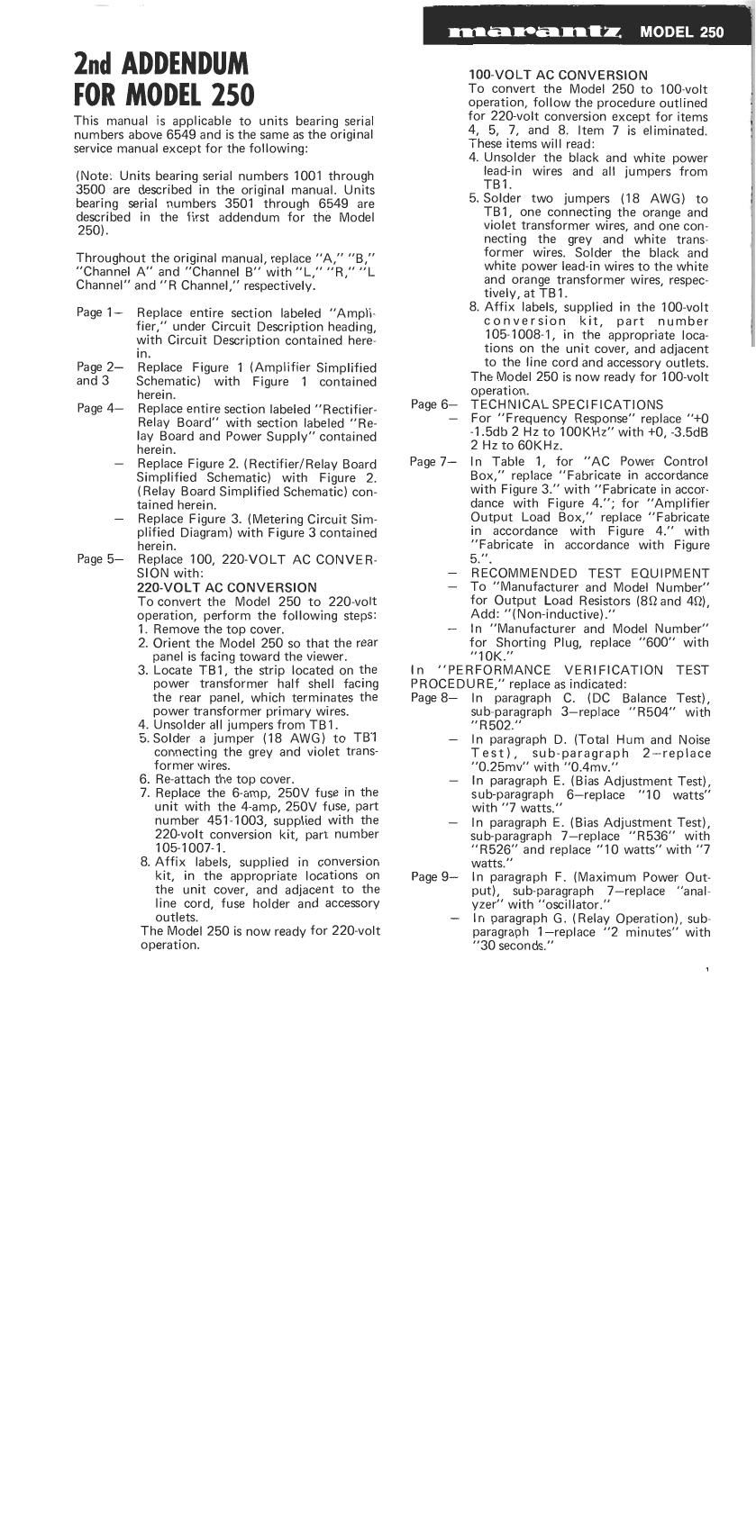
Marantz 250 Addendum 2

This is the 16 pages manual for Marantz 250 Addendum 2.
Read or download the pdf for free. If you want to contribute, please mail your pdfs to info@audioservicemanuals.com.

Page: 1 / 16
left right
Marantz 250 Addendum 2

Extracted text from Marantz 250 Addendum 2 (Ocr-read)


Page 1

2nd ADDENDUM
FOR MODEL 250

This manual is applicable to units bearing serial
numbers above 6549 and is the same as the original
service manual except for the following:

(Note: Units bearing serial numbers 1001 through
3500 are described in the original manual. Units
bearing serial numbers 3501 through 6549 are
described in the first addendum for the Model

250).

Throughout the original manual, replace "A," B,"
Channel A" and Channel B" with "L, R, L
Channel and "R Channel, respectively.

Page 1-

Page 2-
and 3

Page 4-

Page 5-

Replace entire section labeled Ampli-
fier, under Circuit Description heading,
with Circuit Description contained here-
In.

Replace Figure 1 (Amplifier Simplified

Schematic) with Figure 1 contained

herein.

Replace entire section labeled Rectifier-

Relay Board" with section labeled Re-

lay Board and Power Supply contained

herein.

Replace Figure 2. (Rectifier/Relay Board

Simplified Schematic) with Figure 2.

(Relay Board Simplified Schematic) con-

tained herein.

Replace Figure 3. (Metering Circuit Sim-

plified Diagram) with Figure 3 contained

herein.

Replace 100, 220-VOLT AC CONVER-

SION with:

220-VOLT AC CONVERSION

To convert the Model 250 to 220~volt

operation, perform the following steps:

1. Remove the top cover.

2. Orient the Model 250 so that the rear
panel is facing toward the viewer.

3. Locate TB1, the strip located on the
power transformer half shell facing
the rear panel, which terminates the
power transformer primary wires.

4. Unsolder all jumpers from TBI .

5. Solder a jumper (18 AWG) to TB'1
connecting the grey and violet trans-
former wires.

6. Re-attach the top cover.

7. Replace the 6-amp, 250V fuse in the
unit with the 4-amp, 250V fuse, part
number 451-1003, supplied with the
220volt conversion kit, part number
105-1007-1.

8. Affix labels, supplied in conversion
kit, in the appropriate locations on
the unit cover, and adjacent to the
line cord, fuse holder and accessory
outlets.

The Model 250 is now ready for 220-volt

operation.

manoantz. MODEL 250

Page 6-

Page 7-

100-VOLT AC CONVERSION

To convert the Model 250 to 100>volt

operation, follow the procedure outlined

for 220-volt conversion except for items

4, 5, 7, and 8. Item 7 is eliminated.

These items will read:

4. Unsolder the black and white power
lead-in wires and all jumpers from
TBl.

5. Solder two jumpers (18 AWG) to
TB1, one connecting the orange and
violet transformer wires, and one con-
necting the grey and white trans-
former wires. Solder the black and
white power lead-in wires to the white
and orange transformer wires, respeo
tively, at TBI.

8. Affix labels, supplied in the 100-volt
conversion kit, part number
105-1008-1, in the appropriate loca-
tions on the unit cover, and adjacent
to the line cord and accessory outlets.

The Model 250 is now ready for lOO-volt

operation.

TECHNICAL SPECIFICATIONS

For Frequency Response replace +0

-1.5db 2 Hz to 100KH2" with +0, -3.5dB

2 Hz to 60KHz.

In Table 1, for AC Power Control

Box," replace Fabricate in accordance

with Figure 3. with "Fabricate in accor

dance with Figure 4."; for Amplifier

Output Load Box," replace "Fabricate

in accordance with Figure 4. with

Fabricate in accordance with Figure

5.".

RECOMMENDED TEST EQUIPMENT

To Manufacturer and Model Number"

for Output Load Resistors (80 and 40),

Add: (Non-inductive).

In "Manufacturer and Model Number"

for Shorting Plug, replace 600" with

10K.

In "PERFORMANCE VERIFICATION TEST
PROCEDURE, replace as indicated:

Page 8-

Page 9-

In paragraph C. (DC Balance Test),
sub-paragraph 3-replace "R504" with
"R502.

In paragraph D. (Total Hum and Noise
Test), sub-paragraph 2-replace
"0.25mv with 0.4mv.

In paragraph E. (Bias Adjustment Test),
sub-paragraph 6-replace 10 watts
with 7 watts.

In paragraph E. (Bias Adjustment Test),
sub-paragraph 7-replace R536 with
R526" and replace 10 watts with "7
watts.

In paragraph F. (Maximum Power Out-
put), sub-paragraph 7-replace "anal-
yzer" with oscillator."

In paragraph G. (Relay Operation), sub»
paragraph l-replace "2 minutes" with
"30 seconds.

Page 2

marantl MODEL 250

Page 9- In paragraph G. (Relay Operation), sub-
paragraph 3-add Drive both channels."
-- In paragraph G. (Relay Operation), de-
lete sub-paragraph 4.
Page 10- Replace Figure 4. (AC Power Control
Box Simplified Schematic) with Figure
4. contained herein.
- Replace Figure 5. (Amplifier Output
Load Box Simplified Schematic) with
Figure 5. contained herein.
In TROUBLE ANALYSIS, replace as indi-
cated:
Page 11- In SYMPTOM 1.-Replace "(100 watts
or more) with (80 watts or more).
- In SYMPTOM 1. PROCEDURE a.-

Replace " . . . CR301 through
CR304, . . . with . . .CR1 through
CR4, . . ."

- In SYMPTOM 1. PROCEDURE b.-
Replace "Check for open control R224,
215-1005-1 bias assembly" with "Check
for open bias circuit components; 0801,

0521, C513.

- In SYMPTOM 2. PROCEDURE a.-
Replace . . . 215-1005-1 bias assem-
bly with . . , bias circuit components;

0801, 0521, 0513.
-In Symptom 2. PROCEDURE b.-

Replace " . . . CR301 through
CR304 . . . with . . CR1 through
CR4, . . .

- Replace SYMPTOM 3 with Transient
DC voltages at loudspeaker terminals
before time delay circuit is deactivated.

- In SYMPTOM 3. Add PROCEDURE
b.-Check for non-opening relay con-
tacts."

- In SYMPTOM 4. Add PROCEDURES b.
through d.-b. Check for open transis»
tors 0507, 0508, 0510, or 0511. c.
Check for open DC Balance control,
R526. d. Check for leaky or shorted
transistors 0516 or 0517.

CIRCUIT DESCRIPTION

AMPLIFIER

The input of the power amplifier, Figure 1, is an
RF filter comprised of R550 and C501, followed
by transistors 0518 and 0519 which are coupled
together as a conjugate paired amplifier with 100%
feedback. The output of the conjugate pair is
coupled through C502 and R506 to the differential
amplifier, 0501-0502, which drives a high gain
inverter, 0503. 0504 is the current source for the
inverter, and 0520 serves as a current source for
the differential amplifier to enhance its common
mode signal rejection. The inverter is coupled to
complementary pre-drivers, 0507-0508. The out-
put of the prevdrivers is applied to the respective
drivers, 0510-0511, which feed their respective
power transistors, 0802-0804 and 0803-0805.

2

Page11- In SYMPTOM 5.-Add PROCEDURE
c.-Check 0502 for leakage."

- In SYMPTOM 7. PROCEDURE a.-
Replace "Check for defective C506,
(3509, C516, and 0505. with Check
for defective 0505, C506, C508, 0509,
C510, 0516, C518, C519, C520, and
C526."

Page 12- In SYMPTOM 8. PROCEDURE b.-
Replace Check for transistors 0802
through 0805." with Check transistors
0505, 0506, 0516, 0517, 0802
through 0805."

- In SYMPTOM 9.-Replace PROCED-
URE b. with Check output for proper
clipping into 4 ohm load with 25.5 volts
AC output (positive and negative levels
must not vary more than 1 volt at
2KH2).

- Add SYMPTOM 11.-No Output and
add PROCEDURE 3. "Check R529,
0510, 0511, 0802, 0803, 0804, and
0805.

Pages 13-PARTS LIST-The Parts List contained

and 14 herein identifies all parts which differ
from those used in units prior to serial
number 3501.

Page 15- Replace Figure 7. (Power Amplifier
Board Component Assembly Diagram)
with Figure 7. contained herein.

Page 16- Replace Figure 8. (Rectifier/Relay Board
Component Assembly Diagram) with
Figure 8. (Relay Board Component As-
sembly Diagram) contained herein.

Page 17- Replace Figure 9. (Meter Board Com-
ponent Assembly Diagram) with Figure
9. contained herein.

Pages18-Replace Figure 10. (Model 250 Sche-

and 19 matic) with Figure 10. contained herein.

Open loop phase and gain stabilization is provided
by 8 Miller capacitor, 0518, connected between
the collector and base of the inverter (0503).
Further open loop stabilization is provided by
Miller feedback at driver 0510 by C525 and R561,
and at driver 0511 by 0524 and R560.

Output current regulation is accomplished through
a current-sensing network. Excessive current levels
are detected by resistors R531 and R532. Voltages
developed across these resistors are applied to
current sensors 0516 and 0517. When excessive
current levels are detected, 0516 and 0517 de~
velop peak-limiting signals which are applied to
0505 and 0506, respectively. These transistors
disable the pre-drivers on excessive output current
peaks, thus limiting peak output current to the
level determined by the adjustment of R541 and
R542, respectively.

Feedback for the amplifier is developed at the
junction of R531 and R532, and is applied across