Marantz 2238 B Addendum

This is the 24 pages manual for Marantz 2238 B Addendum.
Read or download the pdf for free. If you want to contribute, please mail your pdfs to info@audioservicemanuals.com.

Page: 1 / 24
left right
Marantz 2238 B Addendum

Extracted text from Marantz 2238 B Addendum (Ocr-read)


Page 1

«Qfom! -modulor III-Ii component/-
Pages 57-76 Courtesy Of SUPERSCOPE INC.

Marantz 2238B

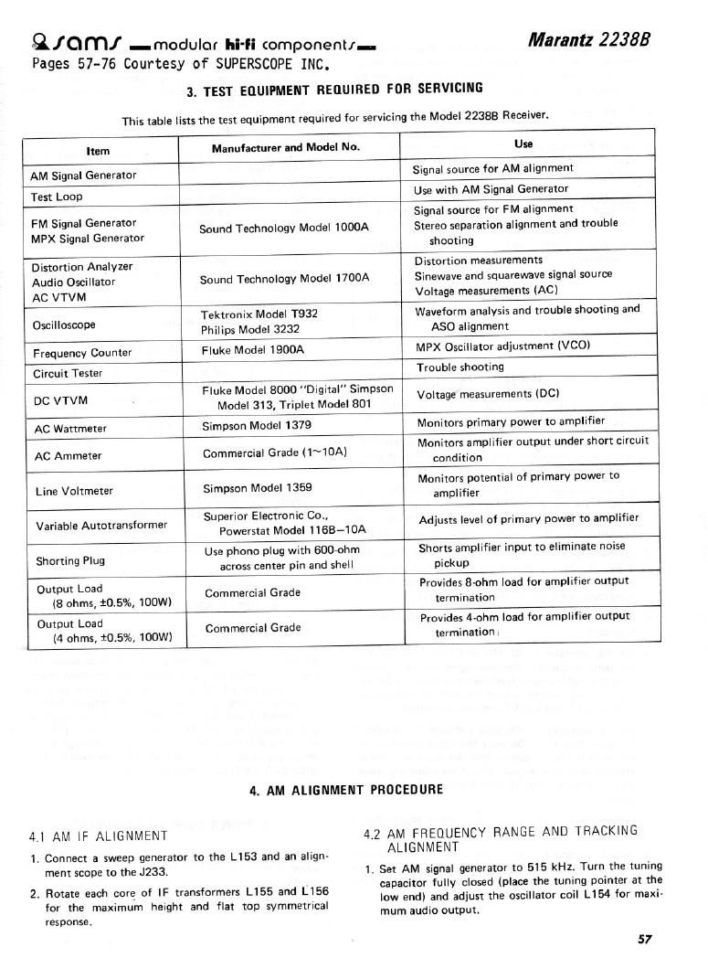
3. TEST EQUIPMENT REflUlRED FDR SERVICING

This table lists the test equipment required for servicing the Model 22388 Receiver.

Item

Manufacturer and Model No.

Use

AM Signal Generator

Signal source for AM alignment

Test Loop

Use with AM Signal Generator

FM Signal Generator
MPX Signal Generator

Sound Technology Model 1000A

Signal source for FM alignment
Stereo separation alignment and trouble
shooting

Distortion Analyzer
Audio Oscillator
AC VTVM

Sound Technology Model 1700A

Distortion measurements
Sinewave and squarewave signal source
Voltage measurements (AC)

Oscilloscope

Tektronix Model T932
Philips Model 3232

Waveform analysis and trouble shooting and
A50 alignment

Frequency Counter

Fluke Model 1900A

MPX Oscillator adjustment (VCO)

Circuit Tester

Trouble shooting

Fluke Model 8000 Digital" Simpson

DC VTVM Model 313' Triplet Model 801 Voltage measurements (DC)
AC Wattmeter Simpson Model 1379 Monitors primary power to amplifier
AC Ammeter Commercial Grade (1~10A) Monitors amplifier output under short circurt

condition

Line Voltmeter

Simpson Model 1359

Monitors potential of primary power to
amplifier

Variable Autotransformer

Superior Electronic Co.,
Powerstat Model 116B-10A

Adjusts level of primary power to amplifier

Shorting Plug

Use phono plug with GOO-ohm
across center pin and shell

Shorts amplifier input to eliminate noise
pickup

Output Load
(8 ohms, 10.5%, 100W)

Commercial Grade

Provides 8-ohm load for amplifier output
termination

Output Load
(4 ohms, 10.5%, 100W)

Commercial Grade

Provides 4ohm load for amplifier output
termination i

4.1 AM IF ALIGNMENT

1. Connect a sweep generator to the L153 and an align-

ment scope to the J233.

2. Rotate each core of IF transformers L155 and L156
for the maximum height and flat top symmetrical

res ponse .

4. AM ALIGNMENT PROCEDURE

4.2 AM FREQUENCY RANGE AND TRACKING

ALIGNMENT

1. Set AM signal generator to 515 kHz. Turn the tuning

capacitor fully closed (place the tuning pointer at the
low end) and adjust the oscillator coil L154 for maxi-
mum audio output.

57

Page 2

2. Set the signal generator to 1650 kHz. Place the tuning
pointer in the high frequency end and adjust the os-
cilator trimmer on the oscillator tuning capacitor for
maximum audio output.

3. Repeat steps 1 and 2 until no further adjustment is
necessary.

4. Set the generator to 600 kHz, tune the receiver to the
same frequency and adjust a slug core of AM ferrite-
rod antenna L001 for maximum output.

5. Set the generator to 1400 kHz and tune the receiver to
the same frequency and adjust the trimming capacitor
on the antenna tuning capacitor for maximum output.

6. Repeat procedures 4 and 5 until no further adjustment
is necessary.

NOTE

During tracking alignment reduce the signal generator
output as necessary to avoid AGC action.

5. FM ALIGNMENT PROCEDURE

5.1 FM FREQUENCY RANGE AND TRACKING
ALIGNMENT

1. Connect an FM signal generator to the FM antenna ter-
minals and oscilloscope and an audio distortion analy-
zer to the TAPE OUT jacks on the rear panel.

2. Set the generator to 87.4 MHz and provide about 3 to
5 AV. Place the tuning pointer at the low frequency
end by rotating the tuning knob and adjust the pitch of
oscillator coil L107 to obtain maximum audio output.

3. Set the generator to 109 MHz and provide about 3 to
5 uV. Rotate the tuning knob and place the tuning
pointer at the high frequency and and adjust the trim.
ming capacitor 0121 for maximum output.

4. Repeat steps 2 and 3 until no further adjustment is
necessary.

5. Set the generator to 90 MHz and tune the receiver to
the same frequency. Decrease signal generator output
until the audio output level decreases with the decreas-
ing generator output. Adjust the pitch of antenna coil
L102 and RF coil L104 for maximum output.

6. Set the generator to 106 MHz and tune the receiver to
the same frequency. Decrease the signal generator out-
put until the audio output level decreases with the de-
creasing generator output. Adjust the trimming capaci-
tors of antenna and RF tuning circuits for maximum
output.

7. Repeat steps 5 and 6 until no further adjustment is
necessary.

8. Adjust the primary core (lower core) of discriminator
transformer L202 so that the center tuning meter
pointer indicates its center at no signal applied. Set the

58

FM signal generator to 98 MHz and increase its output
level 1 kuV and tune the receiver to the same frequen-
cy so that the center tuning meter pointer indicates its
center. Adjust the secondary core (upper core) of L202
for minimum distortion.

5.2 STEREO SEPARATION ALIGNMENT

1. Set the FM signal generator to provide 1 ka at 98
MHz. Tune the receiver to the same frequency so that
the center tuning meter pointer indicates its center.
Then turn off the modulation of the generator, con
nect a frequency counter to test point J229 and adjust
R301 so that the frequency counter may precisely read
76 kHz.

2. Modulate the generator with stereo composite signal
consisting of only L or R channel (of course a pilot sig-
nal must be included).

3. Adjust the trimming resistor R317 for maximum and
same separation in both channels.

53 MUTING THRESHOLD ADJUSTMENT

1. Set the FM signal generator output to provide 12.5 uV
llHF) at 98 MHz and tune receiver to the same fre-
quency. Adjust the trimming resistor R212 for the
threshold level of 12.5 V. (During this adjustment
turn the FM MUTING pushswitch "on".)

54 FM DOLBY LEVEL ADJUSTMENT

1. Set the FM signal generator to provide a 400 Hz, 50%
modulated 98 MHz mono signal, at 1 kuV output.
Precisely tune the receiver to 98 MHz.

2. Depress the FM 251.18 pushswitch, and adjust R215
until the outputs of both channels are 580 mV.

6. POWER AMPLIFIER ADJUSTMENT

Connect a VTVM between R7631+) and R765l-) and
adjust the trimming resistor R731 until the VTVM reads
23 mV DC. And next, connect a VTVM between J717
and J714(GROUND) and adjust the trimming resistor
R711 until the VTVM reads 0 mV DC. Do over again. For
the other channel, connect the VTVM between R764l+i
and R766(-) and adjust the R732 for the same reading,
and connect the VTVM between J718 and J714 and
adjust the R712 for the same reading. Do over again.
When adjusting a DC offset voltage, the switch of the
SPEAKER SYSTEM-1 must be turned on.

1. POWER SUPPLY ADJUSTMENT

Connect a VTVM between J722(+) and J724(-) and
adjust R787 until the VTVM reads 35.0 V under no signal
condition.