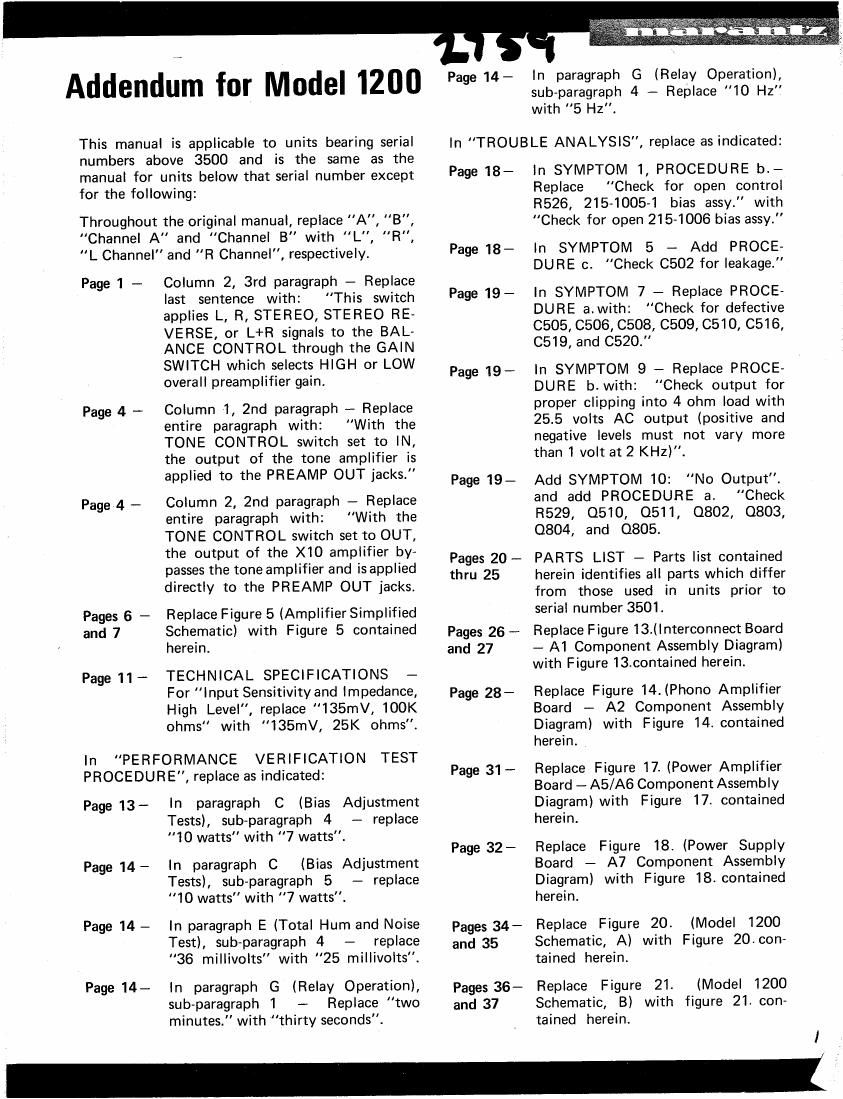
Marantz 1200 Service Addendum

This is the 18 pages manual for Marantz 1200 Service Addendum.
Read or download the pdf for free. If you want to contribute, please mail your pdfs to info@audioservicemanuals.com.

Page: 1 / 18
left right
Marantz 1200 Service Addendum

Extracted text from Marantz 1200 Service Addendum (Ocr-read)


Page 1

This manual is applicable to units bearing serial
numbers above 3500 and is the same as the
manual for units below that serial number except
for the following:

Throughout the original manual, replace "A", B",
"Channel A and "Channel B with ",L "R",
L Channel" and "R Channel", respectively.

Column 2, 3rd paragraph - Replace
last sentence with: This switch
applies L, R, STEREO, STEREO RE-
VERSE, or L+R signals to the BAL-
ANCE CONTROL through the GAIN
SWITCH which selects HIGH or LOW
overall preamplifier gain.

Page1-

Column 1, 2nd paragraph - Replace
entire paragraph with: With the
TONE CONTROL switch set to W,
the output of the tone amplifier is
applied to the PREAMP OUT jacks."

Page 4 -

Column 2, 2nd paragraph - Replace
entire paragraph with: "With the
TONE CONTROL switch set to OUT,
the output of the X10 amplifier by-
passes the tone amplifier and is applied
directly to the PREAMP OUT jacks.

Page 4 -

Replace Figure 5 (Amplifier Simplified
Schematic) with Figure 5 contained
herein.

TECHNICAL SPECIFICATIONS -
For "Input Sensitivity and impedance,
High Level, replace 135mV, 100K
ohms with 135mV, 25K ohms.

Pages 6 -
and 7

Page 11 -

In "PERFORMANCE VERIFICATION TEST
PROCEDURE, replace as indicated:

(Bias Adjustment
- replace

ln paragraph C
Tests), sub~paragraph 4
10 watts" with 7 watts".

Page 13-

(Bias Adjustment
- replace

ln paragraph C
Tests), sub-paragraph 5
10 watts with 7 watts.

Page 14 -

Page 14 - In paragraph E (Total Hum and Noise
Test), sub-paragraph 4 - replace

"36 millivolts" with "25 millivolts.

Page 14- In paragraph G (Relay Operation),
sub-paragraph1 - Replace two

minutes. with "thirty seconds.

Addendum for Model 1200

(Relay Operation),
sub-paragraph 4 - Replace 10 Hz"
with "5 HZ".

Page 14- In paragraph G

In "TROUBLE ANALYSIS, replace as indicated:

In SYMPTOM 1, PROCEDURE b.-
Replace Check for open control
R526, 215-1005-1 bias assy." with
Check for open 215-1006 bias assy."

In SYMPTOM 5 - Add PROCE-
DURE c. Check 0502 for leakage.

In SYMPTOM 7 - Replace PROCE-
DURE a.with: "Check for defective
C505, C506, C508, C509, C510, C516,
C519, and C520."

In SYMPTOM 9 - Replace PROCEv
DURE b.with: Check output for
proper clipping into 4 ohm load with
25.5 volts AC output (positive and
negative levels must not vary more
than 1 volt at2 KHZ).

Add SYMPTOM 10: No Output".
and add PROCEDURE a. Check
R529, 0510, 0511, 0802, 0803,
0804, and 0805.

PARTS LIST - Parts list contained
herein identifies all parts which differ
from those used in units prior to
serial number 3501.

Replace Figure 13.(lnterconnect Board
- A1 Component Assembly Diagram)
with Figure 13.contained herein.

Page 18 -

Page 18-

Page 19 -

Page 19 -

Page 19 -

Pages 20 -
thru 25

Pages 26 -
and 27

Replace Figure 14.(Phono Amplifier
Board - A2 Component Assembly
Diagram) with Figure 14. contained
herein.

Page 28 -

Replace Figure 17. (Power Amplifier
Board - A5/A6 Component Assembly
Diagram) with Figure 17. contained
herein.

Page 31 --

Replace Figure 18. (Power Supply
Board - A7 Component Assembly
Diagram) with Figure 18. contained
herein.

Page 32 -

Replace Figure 20. (Model 1200
Schematic, A) with Figure 20.con-
tained herein.

Pages 34 -
and 35

Replace Figure 21. (Model 1200
Schematic, B) with figure 21. con-
tained herein.

Pages 36 -
and 37


I

Page 2

1' (as? 44;
we? - t

PARfs LIST

Reference Description Marantz Reference Description Marantz
Designation and/or Remarks Part Number Designation and/or Remarks Part Number
lNTERCONNECT
BOARD COMPONENT X10 AMPSOTARD
ASSEMBLY COMPON N
0 c 385 9 ASSEMBLY
c1 1 ., 520 1,:10 ,100v >106
ap '0 % C403 Cap., Elect, 1 1,30%, 381-1055
C102 Cap.,o.1501,¢20%, 250v 386-1022 35v
C103 Cap., 520pf, 110%, 100V 385-1069 0407 Cap., Elect, 1 of, i10%, 381-1055
c104 Cap., 015 01, :20%, 250v 386-1022 35v
R101 Res., C/F, 1K, 15%, 1/4w 434-4102 0414 Cap., Elect, 1 0011091,, 381-1055
R102 Res., C/F, 1K, 15%, 1/4w 434-4102 35"
R103 Res., Variable, Tandem, 420-1023 C417 cap" 5'9" 1 1'11 3814055
35v
25K _
R104 Res., Variable, Tandem. 420-1022-3 040 Trans'smr' NPN 46240382
50K 0402 Transistor, NPN 462-1038-2
R105 Res., C/F, 12K, :5%, 434-5122 0404 Transistor. NPN 462-1038-2
4W 0405 Transistor, NPN 462-10382
R106 $§WCIE 2.7K,:5%, 433-4272 TONE AMP BOARD
COMPONENT
R107 Res., C/F, 12K, i5%, 434-5122 ASSEMBLY
1
MW R307 (Not Used)
R108 . c F 2.7K,: D, 4 3-4272
:2va l ' 5 3 R322 (Not Used)
R113 Res., C/F, 33K, i5%, 434-5332 030 Trans'smr' NPN 462403
1/4W 0302 Transistor, NPN 462-1038-2
R114 Res., C/F, 33K, :5%, 434-5332 0304 Transistor. NPN 462-1038-2
4 0305 Transistor, NPN 462-1038-2
PHONO AMP BOARD POWER AMPLIFIER
COMPONENT BOARD COMPONENT
ASSEMBLY ASSEMBLY
R214 Rest, Variable, 25K, 420-1024 1:505 Cap" 36pr :5%, 100v 3354064
1 4w
/ (3503 Cap., 47pf,110%, 100v 385-1040
R222 R . c F . + 47223
1,64} / '2 meg-1096' 43 c512 Cap., 1000pf,110%, 385-1068
100v
R . v ' -102
235 11223;, arlable, 25K 420 4 C518 (Not Used)
0201 Transistor, NPN 462-10384 C519 cap" 0'1 1110:1096. 250V 3864000
0 . 6 38 -102
0202 Transistor, NPN 462-1038-1 C520 433; 800pf,110%, G 6
0205 Transistor, NPN 462-10384 CR503 Diode 460-1011
0206 Tran5lstor, NPN 462-10384 R501 Res., C/F, 4.7K, :5%, 4334472
1/2w
R508 Res., C/F, 91K, :5%, 434-5912
1/4w