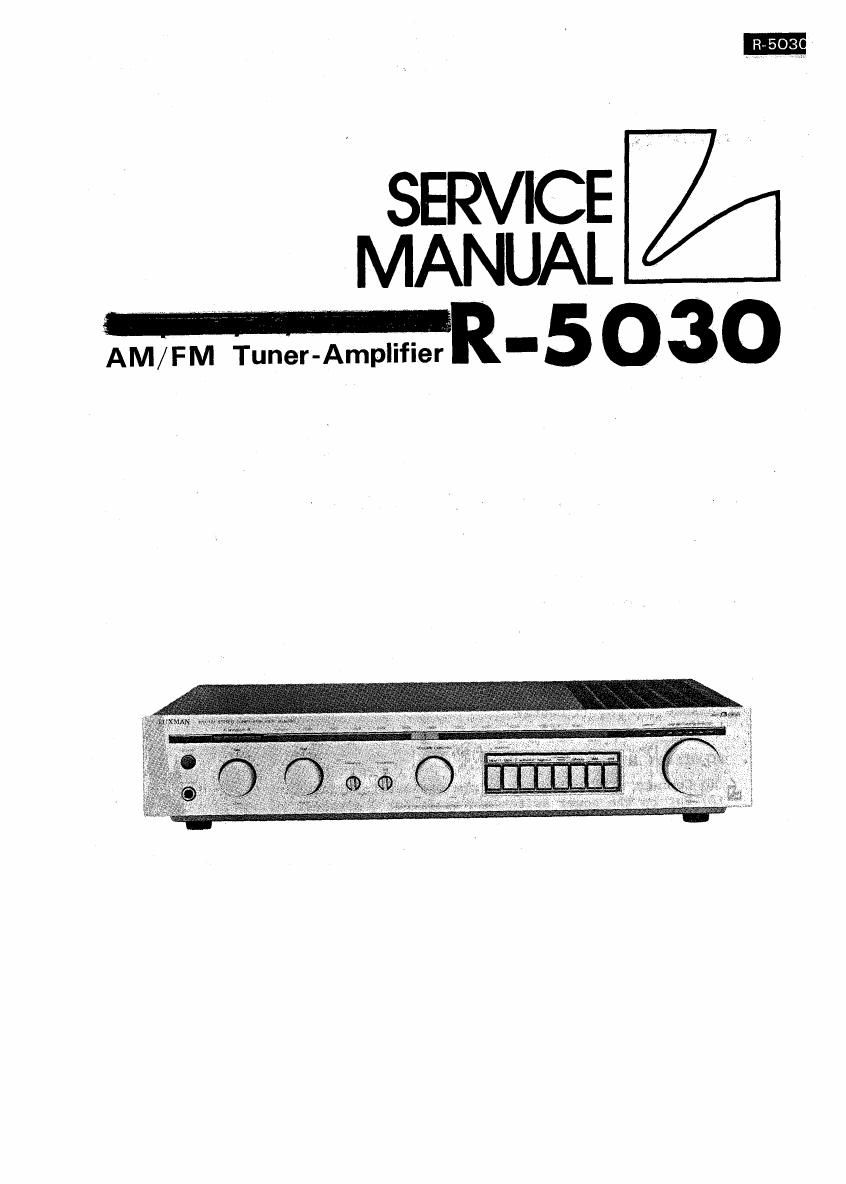
Luxman r 5030 service manual

This is the 22 pages manual for luxman r 5030 service manual.
Read or download the pdf for free. If you want to contribute, please mail your pdfs to info@audioservicemanuals.com.

Page: 1 / 22
left right
luxman r 5030 service manual

Extracted text from luxman r 5030 service manual (Ocr-read)


Page 1

SERVICE
U T MANUAL w
AM/FM Tuner-Amplifier - 5 0 3°

Page 2

-

Contents

Alignment Procedures ............................................ ..... .. l m 4
Exploded View ............................................................... 5
Exploded Parts List' ...............,.......................,................. 6
PB-l396 Parts List 7 7 w 10
PIS-1377 Parts List - 13
PB-l397 Parts List u-a...---.........:....--.e...o....-..................---. 13
PB-l378 Parts List ................................................ ...... 13
PB-1391 Parts List ................... ... 13
SchematierDiagram Audio (UC) ......_ 4
Schematic Diagram Audio ..........r.. 5
Schematic Diagram RF .............;....... . l6
Schematic Diagram RF (UC) .................................................. 17
Specifications .............................................................. 18
Specifications (UC) ........................................................ 19

Receiver Alignment Procedures

This unit was already aligned at the factory prior to shipment but in case that
re-alignment is necessary for any reasons such as replacement of the front-end,
etc., please make alignment with the following procedures:

Audio Section Alignment

1. Set the switches of this unit as follows:

Volume Control : Minimum
Tone Control : Flat
Speaker Selector : A
Balance : Center
Loudness : Off

2. DC Offset Adjustment

(1) Connect a DC voltmeter to the speaker terminals.

(2) Put on the power switch and await for 3 minutes.

(3) Adjuet the semi-fixed resistors, VR803a (L-ch) and VR803b (Rech) on the
PB-l377 to make the DC voltmeter connected to the speaker terminals read
0V.

3. Idling Current Adjustment

(1) Put off the power switch. *

(2) Remove the fuses, F8013 (L-ch) and F801b (R-ch) from the PB-l377 and connect
an DC voltmeter to the terminals. (Be careful about the right connection
to the positive and negative terminals of the DC voltmeter. See Fig. l.)

(3) Put on the power switch and await for 3 minutes.

(4) Adjust the semi-fixed resistors, VRBOAa (L-ch) and VR804b (R-ch) on the

PB-1377 to make the DC voltmeter connected to the fuse terminals read SOmA.