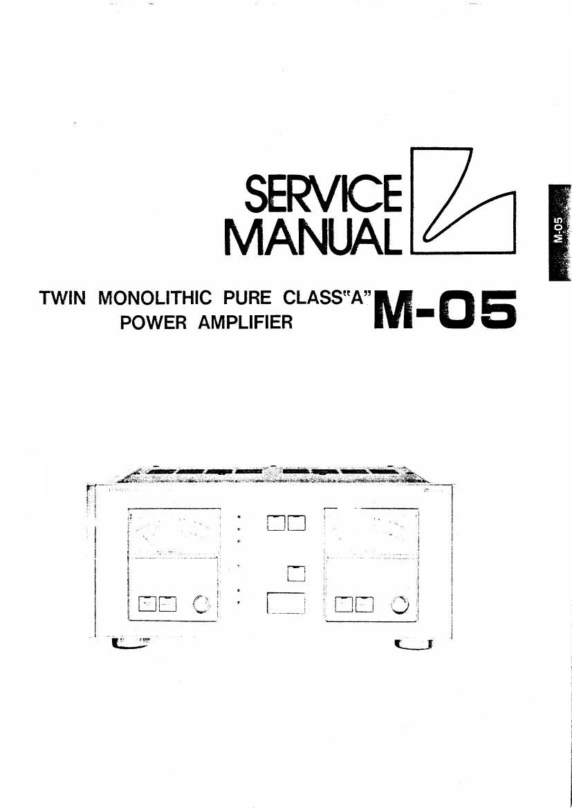
Luxman m 05 service manual

This is the 23 pages manual for luxman m 05 service manual.
Read or download the pdf for free. If you want to contribute, please mail your pdfs to info@audioservicemanuals.com.

Page: 1 / 23
left right
luxman m 05 service manual

Extracted text from luxman m 05 service manual (Ocr-read)


Page 1

SERVICE
MANUAL

TWIN MONOLITHIC PURE CLASSAM 05
POWER AMPLIFIER "

Page 2

Mame/mm new

Contents

Destinations Parts List .
Block Diagrams ......
Adiustment Locations. 1 , .
Adjustment Procedures

Exploded View ................
Exploded View Parts List ..................
Packing Material Parts List ............................................
BTL SW PCB ....................................................
Direct SW PCB ...................................
Main Amp PCB ...................................
Power PCB L/R ........................................
Pre Heat SW PCB . . .......................................
Signal 8: Subsonic PC ...........................................
LED PCB ......................................................
Meter Drive PCB LIR ..............................................
Peak Hold PCB L/R ............................................ 13
LED PCB L/R ................................................ 13
VR Control PCB L/R ............................................... 13
Fan Speed SW PCB .............................................. 13
BTL SW PCB Parts List ............................
Direct 5W PCB Parts List ...........................
Main Amp PCB L/R Parts List .......................................
Power PCB«L/R Parts List ..................................... . ,
Pre Heat SW PCB Parts List ..........................................
Signal 8i Subsonic PCB Pans List ....................................... 17
LED PCB Parts List .......... 17
Meter Drive PCB L/Fi Parts List 7 . ~
Peak Hold PCB L/R Parts List ....... .
LED PCB L/R Parts List ..............
VR Control PCB L/R Parts List .................
Fan Speed SW PCB Parts List ..................
IC Handling Guide ..............................
Schematic Diagram (1) ..............................................
Schematic Diagram (21 ..............................................
Specifications ........................................ t . i .
39, its ...................................................... 22
. . , .
Destination 5 Parts List
5 mm, J 3 SK uz 1
NY) Description Japan Europe USA
' 100V 220V-(240V) 120V
12 Holder, Fuse 09T51828F01 09T51074F01 09T51828F01
16 Cover, Hear 15064791 F01 15D64791 F02 15DB4791F03
20 Housing. Sensor 15BSB781F01 None Use None Use
21 Terminal, Sensor 29A58768F01 None Use None Use
22 Lamp, Neon BNB-Z-C 65T61618F01 None Use None Use
24 Terminal 09T64474F01 Non Use None Use
30 Plug, AC Cord 28T62216F0l 28T65151F01 28T66838F01
31 l Stopper, Cord 43841625105 43841625.!02 43B41625J02
75 Fuse 65T62175F01 65T42077U21 65T62175F01
76 Trans, Power 25T64489F01 25T64489F02 25T66827F01
99 Plate, Serial No. 64A63756F03 64A63756F04 64A63756F07
214 s Screw, MCH, M3x15 03552360F27 None Use None Use
215 l Washer, Spring M3 04840071620 None Use None Use
216 ; Nut, Hexagon 02540000635 None L; c None Use
133 Spacer, Fuse None Use 43A57047F02 None Use

-1_

/\

a MK