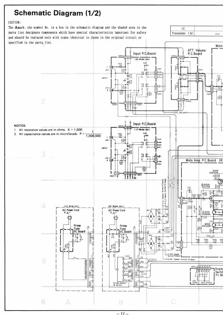
Luxman m 03 schematic

This is the 6 pages manual for luxman m 03 schematic.
Read or download the pdf for free. If you want to contribute, please mail your pdfs to info@audioservicemanuals.com.

Page: 1 / 6
left right
luxman m 03 schematic

Extracted text from luxman m 03 schematic (Ocr-read)


Page 1

Schematic Diagram (1/2)

CAUTION:
The Amark. the symbol No, in a box in the schematic diagram and the shaded area in the IC
parts list designate components which have special characteristics important for safety Translstor (o) m

and should be replaced only with types identical to those in the original circuit or
specified in the parts list.

A ATT Volume | _
E Input PC.Board PCBoard


span? 0450:
up Mm mlyl (E) l
5501 n
a o m 5:;
Jim v m 5 E mm
o to.
I g; *0 I] W m 394-; t.
mm ":1 9 m w o m a
:55 .
t 3g 0 o r.
m z 331 on [L §§ JR
' 39 r 5
we w T
I no :2 # I cam
1 |- 1:750:
IE: <9 mm 3 E
i xi? U
F-anmmon
w-(tw
NOTES: m f input P.C.Board 5
1. All resistance values are in ohms. K = 1,000 1 l (U0 loan my) _I 3 g
2 All capacitance values are in microfarads. P = W Help; H 55: E a -
_ I m. g
40 n
| . §,r_<,u .,1 L"
93 I'M
IIPuv H F '
xi; 0 L
no. gg . on 113- m;
a M; m w Main Amp P.C.Boord (R
I no mo: -- - ,_
3:300) 0203
I. K_ .__1 zsalzos
"$33 - . . +2158
5 =3 _ a 1v
z . :
.3 S '
12%
ES
E
33. 32: 12
r_ _KUO_M0MI£ _ _ up Mod-I my: ' Q E
ac incm i '- 32 , 2" E
| 47A» I I g 3 e E;
I | i . W M
I n Q EE
| l J,
mu SE
| i gas m m.
7 u in m zzx 22
I l 3 23 i
I ' I
I D] [ iifiiiiiéflul
I g 1
®
I I I ES: 3 a 5 a )1
| (3 l I D D
0,"
I I will" mat. a 333m 5502 sssaea
I l -'r sale?! -|
|_ ._ _ _ _ _