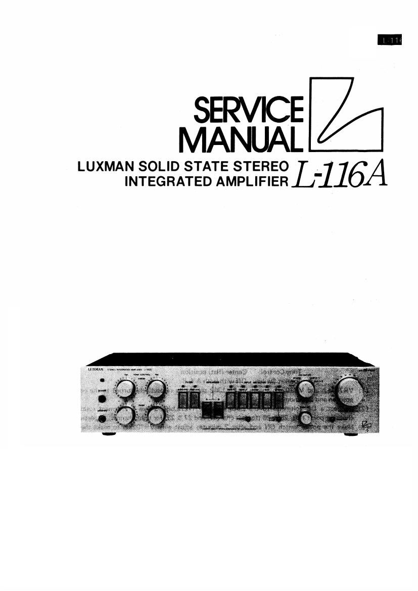
Luxman l 116 a service manual

This is the 12 pages manual for luxman l 116 a service manual.
Read or download the pdf for free. If you want to contribute, please mail your pdfs to info@audioservicemanuals.com.

Page: 1 / 12
left right
luxman l 116 a service manual

Extracted text from luxman l 116 a service manual (Ocr-read)


Page 1

SERVICE
MANUAL

LUXMAN SOLID STATE STEREO _1 1614
INTEGRATED AMPLIFIER

Page 2

CONTENTS

ALIGNMENT PROCEDURES ........................ I
FRONT VIEW PARTS LIST ........................ 2
REAR VIEW PARTS LIST ....................... 3
MECHANISM PARTS LIST ........................ 4
PB-I362 PARTS LIST .............................. 5
PB-l362. PB-l365 PARTS LIST ------------- 6
PB-l363.PB-l364 PARTS LIST ------------ 7
PB-l366.PB-|367.PB-|368 PARTS LIST" 8
PB-I369 PARTS LIST .............................. 9
SCHEMATIC DIAGRAMME ........................... I O
BLOCK DIAGRAMME .................................... I I
STANDARD CURVES .................................... I I

L-116A ALIGNMENT PROCEDURES

L-116A Alignment Procedures

1) Idling Current Adjustment
Setting condition - Volume Control: minimum
Tone Control: Center (flat) position
Speaker Switch: Off with both A & B.
(1) VR701a.b and VR702a.b shown in PB-1362 should be respectively turned to the center
position and left-endmost.
(2) Connect a DC voltmeter to the both ends of R727a.b(0.33-ohm 5W cement resistor),
checking point Nos. 25 & 26 (for left channel) and 27 & 28 (for right channel) respectively)
(3) Make the power switch 0N and after 2 minutes adjust with VR702a.b to make the DC
voltmeter connected in above-mentioned procedure (2) read 33mV.
2) Center Voltage Adjustment
(1) Connect a DC voltmeter to the right and left channels of the spaker terminal "A
respectively.
(2) Push the speaker switch "A and adjust with VR701a.b to make the DC voltmeter con-
nected in above-mentioned procedure (1) read 0V.

* The affix a.b of VFl701a.b & VR702a.b stands for right and left channels.