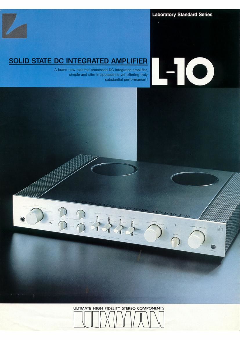
Luxman l 10 brochure

This is the 2 pages manual for luxman l 10 brochure.
Read or download the pdf for free. If you want to contribute, please mail your pdfs to info@audioservicemanuals.com.

Page: 1 / 2
left right
luxman l 10 brochure

Extracted text from luxman l 10 brochure (Ocr-read)


Page 1

Laboratory Standard Series

ULTIMATE HIGH FIDELITY STEREO COMPONENTS

BETWEEN

Page 2

Pure DC Configuration:

The L-10 is a slim integrated amplifier employing the DC
coollgutatlon throughout the entire circuitry Irom the input
stage to the output stage. As musical signals are ol
unrupealable passing nature, to ensure tailhlul
amplification, all the points that play the role at entrance
at each stage have to be 00 contiguratcd. In the case oi
an audio amplilier which deals with music signals. not
only the wave~torrn but also the time lector have to be
taken into account In conventional circuitry design. a
large amount oi NFB has been imposed to eliminate the
dstoriion on the wave-term, while the large capacitor in
the NFB loop triggers time lag. thus increasing phase and
transient distortion. Thus we decrded to remove the
capacitor In the NFB circuit, which inevitably led us to our
unvariable. unique concept-realtime processed" DC
amplllior. The accompanying drawback ol DC drill is
pedectly eliminated by means or our exclusive DMLiC
(Dual Monolithic Linear lCl.

Ultra Low Notch Distortion Equalllng That ol Class
A Operation:

The L-tO otters medium power output. namow. 55W per
channel into 8 ohms loads. both channels driven. lrom
20Hz to 20kHz. with no more than 0.15% total harmonic
distortion. Generally speaking. with an ampliticr or this
output category. the push-pull output circuit is composed
or 2 TO-3 power transistors. But in Uie case ol the bit). to
obtain quick switching speed, 4 pcs. ol 1066 lransrstors
constitute the parallel push-pull circuit. Because oi small
current ihrouoh each transistor, this circuitry otters
excellent treble response and improves the linearity
ensuring larger Po (collector dissipation]. Furthermore,
thanks to the special circuit device at the output stage.
the notch distortion that cannot be remedied even by DC
configuration is thoroughly eliminated. Thus our sooelled
"super-class A" operation enabled us to realize optimum
combination oi the advantages cl both class A and class
B amplillers.

Employment at Tone Compensator:

The L-tD is equipped with the world's first Tone
Oomponsator. which to exclusively designed by LUX to
mare positive compensation on subtle lrequency
response oi disc and tape. Though in its purpose this is
similar to our Linear Equalizer. the Linear Equalizer is
designed to render accurate compensation on the
recording lrequency response. while the new Torte
Cornpensetor is designed to create a certain lrequency
response in the pogram source. This Tone Compensator
is so designed as to obtain the specified response curve
starting (rpm the -6dB position of the volume controL
partly to avoid active components and partly because
human ears are less sensitive at high volume level. The
has turnover can be selected among SDHZ. 20on and
room. while either at 700Nz. 3ki chosen in the item 13090. Adjustment can be We in
the range + 2d8~-2.5dB in accordance with the turning
angle oi normal potentiometer. and subtle compensation
is allowed on the trequency response ol program source.
Note that unlike the tone control the amount oi variation
is small and that compensation oi speakers or room
acoustic is not leastble with this control.

Improvement ol Cannot Separation and Other
Characteristics Which Deieriorate Tonal Ouallty:
To improve channel separation and to prevent overall tonal
degi'adalion. the wiring is separately arranged lcr both
right and tell channels with the shortest length especially
at speaker terminals where large current flows
Furthermore. the independent power supply sections in 2
dillerent pn'nted circuit boards are provided at the right
and leit channels with the separate hl9h~elliciency low-
lcsrago toroidal power transformers in combination wllh
largevcapacltance lowlmpodahco electrolytic condensers
(6,800pr4). Naturally the relays for muting circuits and
speaker terminals are lndependonL We set up only 1
channel at phone input directly coupled to equalizer in
order to prevent deterioration or channel separation at
selector section. as most popular MM type aartrldges oller
high impedance (SM-60K ohms) in the treble (above
tokl-lz) though usually 3K ohms at tkHz. Needless to SOY.
meticulous wiring is rendered at all the circuits.

Subsonic Filter:
Such noises In the ultra low irequencios as are caused by
warps oi disc. resonance ol tonearm, mmbie or phono-

motor and acoustic teedback otc. range lrorn 5H2 to
5OHZ. Even out ol the audible range below 20Hz. these
cause a harmful lntermodulatlon distortion tiy activating
the cone ol loudspeakers. The Suhsonic Filter is provided
with 2 cut~oll Irequenciea at will and 20m to ellcctivoly
retrieve these unwanted noises ol ultra low lrequencies

New Type Volume Control:

Conventionally. high-class amplifiers are equipped with
the detenl volume because of its reputed predation
despite the demerit that minute control is not possible
especially at the low level due to click~stop increments.
But originally the volume level ha in be continuously
controlled. In this respect we made tunhor study on the
detent type potentiometer. and the new one was
completed. Not only the continuous variation is possible
in volume level. but also the gang-error between the right
and tell channels is maintained below 1/2 in the wide
range trom Ode to -30dB. which could not be realized by
a oonventiorul potentiometer ol continuous variation. This
is comparable to that ol the detent type potentiometer.
Needless to say. thorough study is rendered on tonal
quality.

TAPE-t Recording Selector
Filter Switch
'Treble Control

mmmg

Mode Selector Smith
Tone Deieat'Swltch

Headphone Jack

'Trebie TunioverSeleclor Switch
Bass Turnoversoiector Switch

'Tone Oompomator

TAPE-2 Recording Selector
Tape Monitor Switch

Balance Control
. AC Power Switch

L -10 SPECIFICATIONS

Power Output:

55 watts minimum continuous per channel into 3 ohms load. both channels

driven. at any lreouenoy lrom 20Hz to 20.0sz with no more than 0.015%
total harmonic distortion.

no more than 0.015% (8 ohms. 55W. GJHI : 7kHz = A: l)

so (8 ohms. litHz)

WEEensltlvlty:
signal-to-Nolse Ratio:

phono.

input Equivalent rife-.57

phono; GmV. tuner au soomv main ln; soomv

no less than 9008 (iHF A w
tuner. aux; no less than 10063 HlF-
rnoln in' no loss than 1308 (IH A weigh

phono: no more than -i3IdBV (li-IF- A weighted, input shortcircuited]

riled. input tomVinpul'short- circuitedl
weighted inputshort- -'c uited)

tuner. no more than -111 dBV (IHF- A weighted. input short crrcuited)
main in; no more than -ttt d8V (IHFA weighted. inpurshort-clmultod)

Frequency Response:

phone; 20H2-2Qotxll-lz (:OZdBj

tuner. aux; oc-woooom (-l dB)
main in: DC-leOOHz (-105)

fire'ArrElsutpifi Voltage:

pm. out: typical WNW. max 18V

rec. out: typical soomv. max 18V

fond caramel?

variable range: + 209. -7_5d8 maximum (continuously variable)

Bass Turnover Frequency: SOHL ZOOHL 700H 2
Treble Turnover Frequency: MHz. Skit. tOkHz

Protection Circuit:

Speaker Protection Circuit by sensing DC voltage

Excessive Current Protection Circuit

other Features:

Subsenic Filter (10H). normal. 20Hz). TAPEvt Recording Selector (lrom-i.

source, rec Dill. TAPE-2 Recording Selectorilromtz. source. rec. oil) Tape
Monitor Switch (lapel. source tape 2) Headphone Jack, Extra AC Outlets
(SWITCHED. unswrrcrrED)

Power Consumption:

230W (8 ohms. maximum output)

mVA (GSA rated)
dimensions: 638M) x 153(0) x 78(Hlmm (17-lld" x 1449/64" x 35/64)
Weight: Net rooms (231 lbs)

Gross tackgs maths.)

Specifications and appearance design are subject to possible change Without notice

LUX CORPORATION, JA AN

l t. l CHOME. SHINSENRI NISHIMACHI, TOVONAKA-SHI. OSAKA PHONE 06834-2222 CABLE LUXELECY OSAKA TELEX .1635?

Primed Ill Japan