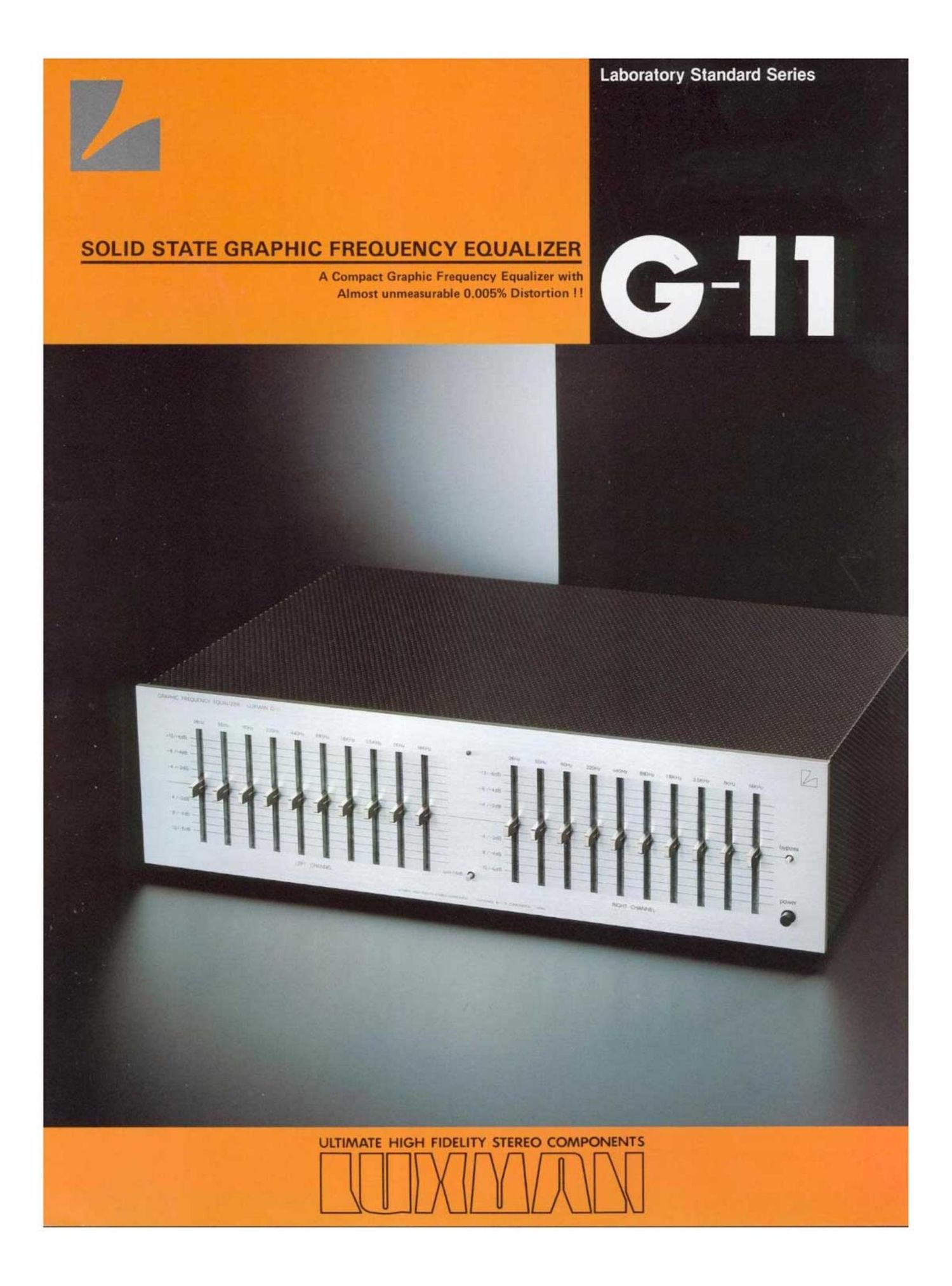
Luxman g 11 brochure

This is the 2 pages manual for luxman g 11 brochure.
Read or download the pdf for free. If you want to contribute, please mail your pdfs to info@audioservicemanuals.com.

Page: 1 / 2
left right
luxman g 11 brochure

Extracted text from luxman g 11 brochure (Ocr-read)


Page 1

Laboratory Standard Series

Page 2

CIRCUITRY:

Unlike conventional graphic equalizers using LC
resonant circuits. the entire control circuitry of
the (3-11 features semiconductors and capacitors.
which makes it possible to offer not only an
unrivalled 0.005% total harmonic distortion and
intermodulation distortion even at 2V output

but a superb S/N ratio exceeding 110d8 (lHF
A-curve).

Functions:

The audio frequency range for both right and left
channels is divided into 10 bands in 1 octave
increments based upon the "A" tone, (440Hz)
which is the standard tone of musical instruments.

to center-frequency points are provided for each
channel. which permit adjustment of the peak
and dip at each point. enabling you to create
whatever frequency response Curve you want.

Overall selection of the maximum variable amount
of peak and dip can be made by 2 steps (:BdB
and t12dB), which allows such operations as
manual tone control for large tonal variations

or as in the case of our Linear Equalizer for
small variations. Therefore. you can enjoy wide
range compensation of frequency response, such
as frequency compensation of loudspeakers or
phono cartridges, optimum control of room
acoustics. compensation of RIAA curve. or
frequency compensation of tapedecks, etc.

A bypass switch is also provided to check the
effect of this equalizer and to compare equalized
and unequalized response.

We know the true measurements of minimum
performance standards of a quality amplifiers must
be of a very high level. However. these figures are
not the only requirements. Despite every effort to
make amplifier design a pure science one amplifier
among many with similar absolute specifications
can still have. relatively. far better sound quality.
The reason there are more comprehensive theories
of amplifier design which account for such problems
as harmonic and intermoduiation. and notch
distortion; stability, filters, and equalization as
they relate to statements of power.

Whatever the scientific theory. LUX conducts

the most detailed listening test with engineers

and musicians in different fields to ensure that
LUX amplifiers sound best apart from what is
considered good in brochures.

To LUX.sound is not only a science but an art.
Listen to the ultimate difference at your nearest
audio shop.

mm vs. mnldmhumafl

us
0

RESPONSE (as) +
O

l
out
0

- 20
20 50 IN 200 m 1k 2k 5 k 10k mk
FREQJEW (H!)
i. .0. in. w LEEI. w
(Numb-mammul. at) Mk-nammutefl
T ' -

q-rraiifiwi - I'VIo

¢i7+ 0 .+.+«-i

WIN" film

SPECIFICATIONS

Output Voltage: typically lV, max. 6V (at flat position)
Output impedance: 500 ohms

i. H'. 1).: " i-no more than 0 005%

9 7 7 (output 1V, 20H: - 20 9024;, fiat)
l.M.D.: no more than 0.005%

(output 1V, 60Hz: 7kHz = 4 1, flat)

Input Sensitivity: 1V
input impedance: 100k ohms

Frequency Response: 10H: - 100. OOOHz
(within -1dB at flat position)

OdB (within 20. 5d8, at flat position)

Gain:

SIN Ratio:
better than 95d8 (at flat position. RMS, input shortcirCuited)

Equalizer Center Frequency:
Maximum Variable Amount: :12dB 81 :6dB (selectable)

better than 115dB (at flat position IHF A weighted, input short-cirCuited)

28Hz,55Hz,110Hz,220Hz,440Hz, 880Hz,1.8kHz.3.5kHz, 7kHz,14kHz.

inseam; o 4-. 2.3
Channel Separation: better than -80dB likHz)
Residual Noise: below 0 018mV (at flat position)

Additional Fa_aturas:

Power Consumption: 23 W

Range selector Switch, Bypass Switch, Extra AC Outlet (unswitched. 300W)

Dimensions: 438(W) x 314(0) x 126(Hl mm (17-1/4" x123/8" x 4-15/16")
(including legs. front & rear protrusions)

Waidtt: Net 5.9 1:95 (12.9 lbs.)
Gross 7..3kgs(l61lbs.)

Specifications and appearance design subject to change without-notice.

LUX CORPORATION, JAPAN

NAAA~ti l\-_~