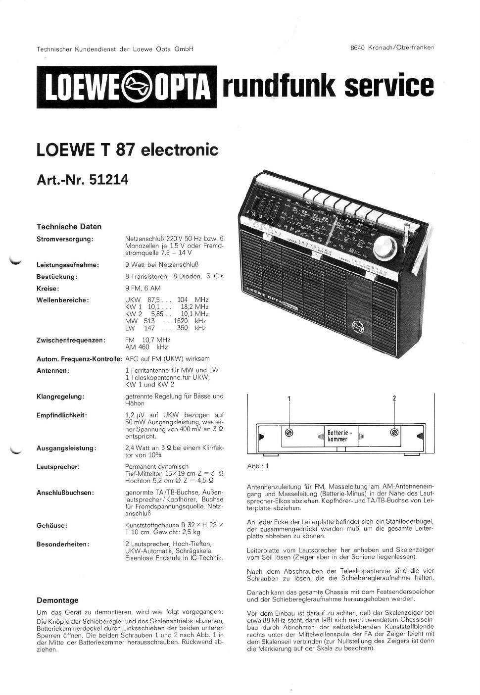
Loewe t 87 service manual

This is the 14 pages manual for loewe t 87 service manual.
Read or download the pdf for free. If you want to contribute, please mail your pdfs to info@audioservicemanuals.com.

Page: 1 / 14
left right
loewe t 87 service manual

Extracted text from loewe t 87 service manual (Ocr-read)


Page 2

Abgleichvorschrift

Allgemeines

Das Gerat wurde In unserem Werk soigfaltig abgeglichen Abe
gleicharbeiten am FMV und AMVHF-Teil sollten nur dann vorge»
nommen werden, wenn bei der Uberprulung des Gerates alle
sonstigen Fehlei srcher ausscheiden.

Notwendige MeBger'ate

AMrFlvlrMeBsender von 140 kHz bis 110 MHz 60 Q Ausgang,
ZFrWobbler und Oszillograt

UnlversalmeBinstrument (Outputmeter)

Vorbereitungen zum Abgleich

Alle Abgleicharbeiten sollen bei 9 V Betriebsspannung verge-
nommen werden Vor dern AnschluB der MeBgerate erst die
Masseverbindung mit dem Prijfling herstellen. Drehkondensar
tor voll eindrehen, Skalenzeiger aut die Skalenendmarke ausV
richten. HF-Eingangsspannung so bemessen, deli max 400 mV
(50 mW an 3 $2) an den Lautsprecherbuchsen nicht Uberschnt-
ten werden.

Damit die Skaleneichung auch stimmt, istzu BeginnderAbgleichs
arbeiten zu kontrollieren,ob die Unterspannung von 5V am Meli-
punkt ®, bei derSkalenzeigerstellung an der unterenSkalencndr
marke, und die Oberspannung Von 20 V am MeBpunktTi, bei
der oberen (rechten) Skalenzeigerendstellung, vorhanden Ist;
andernfalls mit dem RegelWIderStand P 104 iiir die Unterspanr
hung und P 105 lur die Oberspannung nachstellen

Abgleich ist so lange Zu Wiederholen, bis Abgleichpunkte aul
derSkala mitSignalfrequenz ubereinstimmon und die maximale
Emptindlichkeit und Kurvensymmetrie erieicht ist,

Technical data

Mains 220 V 50 Hz resp, 6 mo,
no cells of 1,5 V each or exter-
nal power source 7,5 - 14 V

Current supply:

Consumption: 9 W when mains operated

Transistors etc.: 8 transistors, 8 diodes, 3 lCs

Circuits: 9 FM, 6 AM

Wave ranges: FM 87,5 i . . 104 MHz
SW 1 10,1 H, 18,2 MHz
SW 2 5,85 i ,, 10,1 MHZ
MW 513 . . 1620 kHz
LW 147 . . 350 kHz

Intermediate frequencies: FM 10,7 MHz
AM 460 kHz

Automatic frequency controleFC effective on FM

Aerials: 1 ferrite rod antenna for MW
and LW 1 telescopic aerial for
FM, SW 1 and SW 2

separate bass and treble con-
trols

Tone control:

1,2 W on FM in relation to
50 mW output power, which
corresponds to a tensron of
400 mV at 3 5'2

2,4 W at 3 Q at a distortion fac-
tor of 10%

Sensitivity:

Output power:

Loudspeaker: permanent dynamic
woofer and medium-tone
13><19 cm 3 Q
tweeter 5,2 cm (23 4,5 9
Sockets: standard PU /TR socket, exter

nal speaker/headphone, sokr
kets for external power source
and mains supply

Cabinet: Plastic cabinet W SZXH 22X
D 10 cm. Weight' 2,5 kg.

2 loudspeakers, tweeterrwoo-
fer, Flvl automatic, inclined dial.
OTL (power) output stage in
lC technique.

Miscellaneous:

Dismounting

In order to dismount the set, proceed in the following manner

Pull off knobs of the sliding controls and dial drive, open lid of
battery compartment by pushing the two lower locking devices
to the left Loosen and take out the two screws 1 and 2 in the
center of the battery compartment (see fig 1) Pull off back panel.

Pull oil antenna input lead for FM, mass lead at antenna input
and mass lead (battery minus) near the electrolytic Condenser
ofthe loudspeaker. Pull of headphone- and PU/TR sockets from
printed circuit board.

A steel spring bow is prowded at each corner of the printed
Circuit board, ln order to be able to lift off the entire board, com-
press these bows and take out board, lifting it from the speaker
Slde and loosening dial pointer from the cord (leave pointer in
the rail)

Alter having screwed oh the telescopic aerial loosen the four
screws holding the sliding control aggregate:

Thereafter the entire chaSSis With memory tuning devrce and
the sliding control aggregate may be lifted oft,

Before remounting the set, care must be takenthal the dial pomr
ter stands at about 88 MHz, thus 1 after remounting of the
chassis has been completed - faCilitating the re-connection oi
the pointerto the cord. For this procedure take off the self-stik-
king plastik mask atthe right hand Side below the medium wa-
ve coil of the ferrite rod antenna. (for zero pDSition of the poinr
ter, watch respective mark on the dial).

hummer
l |

"I" 0 fl Butteric - F]. 0 lfl

Fig 1