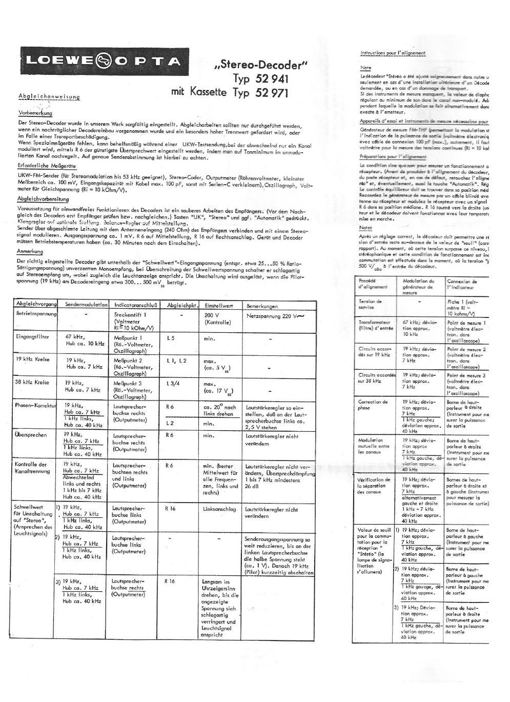
Loewe stereo decoder 52941 52971 service manual

This is the 4 pages manual for loewe stereo decoder 52941 52971 service manual.
Read or download the pdf for free. If you want to contribute, please mail your pdfs to info@audioservicemanuals.com.

Page: 1 / 4
left right
loewe stereo decoder 52941 52971 service manual

Extracted text from loewe stereo decoder 52941 52971 service manual (Ocr-read)


Page 2

M dam no": u ine. 3e Jawb- d'ai'g-eu devraiend ene faires
e d'un Decode'r et si are were seize-nee #cialement haute est

part.
:larrda diaphc-iie I- as w are: ceeaéome par mayen de R 6 on
n-modulé. Adoptex 3-. me =96!th grandad UB1 omission FM d'eeai
.ativernenr data an seu as m. Fifi: mien a une synranisation

59min: E y i'allm

a modulation stErénp'i'u'Itaae 353': E at, Reta-weer, instrument paur
err: sleetrpaique para a: 52m I-uonv, acquire d'entree
ran-mi, il laut di in: c auxf'é. M an série), oscilloscope,

res (Xi = 10 kolrnx/V).

miennemenr cirrrecr a. new a re fiancimm impeccable do

it do déoodeur, il fan, :I:' m, veifiu ie imdionnemenl regulier

ruchei l'ullgnement 0: "net. Mane: la laud: 'UK" (FM), 'Sté»

ilamatik". Reglez la 'arcc-e 3: dark la aieilleure reproduction.

a Positlm mediane.

ble hlindé aver: let bans few-:6: 2Q daze): lo maxim de Pan-
ivec uri rignal stereapten'ae. Baku-dcéewfl environ lmv.

rs In drain jusw'a Ir: hrée. Jam! & m l'alw, Ie réep-
Ieur lempemm'e ml: ea Ewing, use-B1: mm admire. QvB la

armreflre une réceptlen me it: GWEN, a? [e nTvaad de la ten-
e seull'(aan:spami:rtaE-3)%delatmiundemmiwde

mement est rid use are I'allm de la terrace de signalisation. La

T-e srerec Decoder has been caretully adjusted in our fudary. Alignment operatt'ons should be carried through <
wmn a subsequent installation at a decoder was made, and it a specially high value'af selectivity is required, r
moms has been damaged during transport.

H special measuring lnslruments are not at hand, the most favourable truss-talk value can he set through R a by
iusting to the minimum sound in the unmodulated channel. Take this auxiliary measure during an FM test transmi
where the modulation is done in me o! the channels alternatively. Careful and exact syntanisatian with the trar
mirter should be observed.

Testing egulEment, reguired for the alignment

FM-VHF signal generator (permitting stereo modulation up to 53 Kc/s), stereo coder, output meter (valve valtm
lowesf measuring range approx. loo mV, input capacity should be diminished), oscilloscope, d.c. voltmeter (Ri
10,000 ahms/valt).

Preparations For the alignment

The primary condition for the proper operation antic decoder is, of course, a satisfactory performance of the net
(The receiver should, thereiere, he tested and, eventually, realigned, baiore aligning the decoder.) Press the 5
UK" (FM), Stereo" and, eventually, "Automallk". Set lone control for best reproductian. Balance control shi
be in its mid-position.

Connect signal generator by means at is screened cable to the antenna inpui terminals (240 ohms) at the receiver
which should be modulated with a stereo signal. The output voltage should have a value otupprax. 1 mV. R 6 sl
he in its mid-position and R l6 turned to the right-hand stop. Fora proper alignment, the receiver and the deco
should have their regular operating temperature (warming-up time about 30 minutes).

Remarks
E the M has been properly ted, il will pmlae undistorted Wml reception hole the "th held'
0? "l2 ii-pc- vol-o9: (carespmding to about 25 to so is of lhe ratio-saturation voltage). Above the threshold va

the decoder will suddenly switch over to stereo reception and lhe indicator lamp will light up. This switch-over
take place, when rhe pilot voltage (19 Ke/s) at the input of the decoder reaches a value of about 300 to 500 m

a la tension "pilote' he )7 kHz)arteirtt une valcur denviron 300a Alignment procedure Modulation of Connection at Paints tar Proper Remarks
signal generator indicator alignment adiusiment
_ Opemiing voltage - Plug contact 1 - 200 v (check Mains voltage
'fm" 4° f" e W 95 (voltmeter Ri this voltage 220 v A.C.
mm 9" , 10,000 ohms/volt)
a l (IF 7 av MY; 0!.de a Input transformer 67 Kc/r; devia- 'lestpoint i (valve L5 min. -
a R, = Pu m 220 V;.u. (filter) tian approx. voltmeter in
MM Wm} io Kc/s escillascope)
r... mm 1 L 5 ,g._ _ l9 Kc/s-circuits l9 Kc/i; devia- Test point 2 (valve L l, l. 2 max. (about
metre éleb tion approx. voltmeter in 5 V ) -
. dons 7 Kc/s oscilloscope) PP
meme) l r . , r
as Kc/s-crruiits l9 Kc/s; devia- Test paint 13 (valve Lil/4 max. (about
ids unsure 2 L L L2 in: lead: . rion approx. voltmeter in I? v ) -
"3:: step race . at: ; 7 Kc/s oscilloscope) 9
:illaseepe) ; Phase correction l9 Kc/s; devia- Loudspeaker socket R 6 Turn abmt 20" Set volume ccntrr
rd: new 3 L3/ L m i lion aparwr. right (outpui- in counter- about 2,5 Vare r
mg". 41¢, a, 37 v ck) . meter) clockwise at left speaker SOl
3mg direction
:llloscope) L 2 min.
a d. ham- R 6 Tau-.2: when. file: I: velar:
-ur mite 20 ewe-s In , lam/h w: Crass talk l9 Kr/r; aevza- Mpeaker socket R 5 min. Do not change ad
went pour me- each: when 2,5'1 a: la tier. approx. right (outpur- at volume control
la pusssarlCt: L 2 Kim I! gee-ch. tie l~a.r- 7 KC/S mm)
W '4 Left l Kc7s;de-
viatian approx.
A de quI- R 6 l min. Ne Che-0991 pas lulvsie A0 Kc 5
:m' a aroite l merit du volume
WM pour me. Checking channel i9 Kc/s; devie» Loudspeaker suckers R a min. (adiust Do not change ad
in wrung: 1 separation t' n approx. right and left for best mean of volume control
csze 7 c/t (Output-meler) value tar all talk damping trarr
l Alterna ely frequencies Kc/s at least 266
5 3 MW R o I if Ne cm: pas Mam, leit and right lett and right
or odraite et (ceiliatae va- or volume. Ansmtation d: Kc/S 7 KC/S;
.ahe (iratnrrncn I leur lEdlcne la modulation mile entre dcvialion
mutter la pour rarer la i- 7 Lra, ad aarezs dLr aporcx. 40 Kc/s
once de sonic) : WEE, ,
. 913. e. Threshold value l) i9 Ke/s; devia- Loudspeaker socket R l6 Turn lo leit- Do not change set
M.) (as witeh~aver rian approx. left (armor-meter) hand stop volume control
to 'Sr 7 Kc/s
: ae MW R M f T m {fun-l 1:er m
uragouchc l egg \- I lightup) viatian approx.
umenr pour me- ' 'esxi: c 40 Ke/s
If Pu'swnw : e19 2) w Ke/s; devic- Louruaeclrer sacket - - Output voltage at
"" i , tion approx. ietr (output-meter) generator should I
; 7 Kc/s minished until hal
ide iaut- - 2 v 3mm to reason desa- W tage (approx. 1,:
ur a gauche » rte a1 eta-elm; oe rfin, viation approx. measured at the l.
umem pour me- i run 5 {ate} heed 40 Kc 5 ker output. Then,
la puisrcnoe l as e ester temrm LG V} err 19 Kc/s (pilot
trio 1 hooves-acted: 3) l9 Kc/s;devlu- Laudspeahersacket R l6 Turnxlowly ln hm .ad h.
htwwfimf: '59- tian approx. right (Output-meter) a clockwise di- Fe" °
. _ - u. I mm W "" 7 Ke/s reclion, until
Liz-3n R 6 :2; is: °" W" l '9 kH) Leit l Kc7s; dc: ' indicated val-
ument pour me» a-a": isn't-I saudalnemont viatiorr approx. rage is suddenl
la puissanoe m a: la .. tr, imp. g. 40 Kc/s diminished and
rrie 1-5::- eis- xtwairmtim signal lamp
ah aha-u: s'nllume. lights up.