Lg dvd 3230 n service manual

This is the 39 pages manual for lg dvd 3230 n service manual.
Read or download the pdf for free. If you want to contribute, please mail your pdfs to info@audioservicemanuals.com.

Page: 1 / 39
left right
lg dvd 3230 n service manual

Extracted text from lg dvd 3230 n service manual (Ocr-read)


Page 1

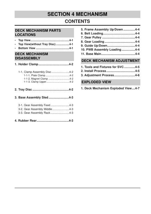
SECTION 4 MECHANISM

CONTENTS
DECK MECHANISM PARTS 5. Frame Assembly Up/Down .............. 4-4
LOCATIONS 6. Belt Loading ...................................... 4-4
_ 7. Gear Pulley ....................................... 4-4
- Top View ....................... ..4-1 8. Gear Loading... ------ 4_4
- Top View(without Tray Dlsc). ..4-1 9_ Guide Up/Down.... 4_4
- Bottom View ........................................... 4-1 10. PWB Assembly Loading IIIIII 4_4
DECK MECHANISM 11. Base Main ........................................ 4-4
DISASSEMBLY
DECK MECHANISM ADJUSTMENT
1. Holder Clamp .................................... 4-2
1. Tools and Fixtures for SVC ............. 4-5
1_1_ Clamp Assembly DlSC _______________________ 4_2 2. Install Process .................................. 4-5
1-1-1. Plate Clamp ........ ..4»2 3. Adjustment Process ......................... 4-6
1-1-2. Magnet Clamp ..4»2
1-1-3. Clamp Upper ................................. 4»2 EXPLODED VIEW
2. Tray Disc ........................................... 4-2 1- 99"" MeChanism EXP'Wed View-"4'7
3. Base Assembly Sled ........................ 4-3
3-1. Gear Assembly Feed ........................ 4-3
3-2. Gear Assembly Middle.
3-3. Gear Assembly Rack ........................ 4-3

4. Rubber Rear ...................................... 4-3

Page 2

DECK MECHANISM PARTS LOCATION

. Top View (With Tray)

Procedure

. Bottom View

. Disass Fi -
Starting N0. Parts Fixing Type embly urge
1 Holder ZScrews, 4-1
Clamp 2 Locking Tabs
1 2 Clamp Assembly 4-1
0150
1,2 3 Plate Clamp 4-1
123 4 MagnetClamp 41
I 2 34 5 Clamp Upper 4-1
1 6 Tray Disc 42
I 6 7 Base Assembly Sled 43
4 Screws,
1,2,6 8 GearAssembly 1Connector 4-3
Feed 1 Locking Tabs
126,8 9 Gear 43
Middle
1 26,8 10 Gear Assembly 1 Screw 4-3
9 Rack
1 2.7 11 Rubber Rear 43
1,27 12 FrameAssembly 1Screw Bottom 44
Up/Down
12 13 Belt Loading 1 Locking Tab 44
1 2,13 14 Gear Pulley 4-4
1 213,14 15 Gear Loading 1 Locking Tab 44
127121314 16 Guide Up/Down 4-4
1 2,13 17 PWB Assembly 1 Locking Tab Bottom 44
Loading 1 Hook
ZScrew
1 2. 7 12 13 18 Base Main 2 Locking Tabs 44
14 15.16117
Note

When reassembling, perform the procedure in
reverse order.

The Bottom" on Disassembly column of above
Table indicates the part should be disassembled
at the Bottom side.