Leslie combo preamp ii service manual

This is the 2 pages manual for leslie combo preamp ii service manual.
Read or download the pdf for free. If you want to contribute, please mail your pdfs to info@audioservicemanuals.com.

Page: 1 / 2
left right
leslie combo preamp ii service manual

Extracted text from leslie combo preamp ii service manual (Ocr-read)


Page 1

PRE-AMP 11

GREEN1.)
VOLUME 04° l our @
CONTROL
2 9 Q
; >
soon a
RI = 2 " a
B 2
n m 2
- x 4 a
m. ig :2 u 3 U SPEAKERS
10K I
:42 .l
, , m 0, m .@ COMBO PRE-AMP 11
W , , ' Eo
+ ELECTROLYTIC L. Eloiflglggvm + - m
@ mm 50v cu [E @
_ , , an
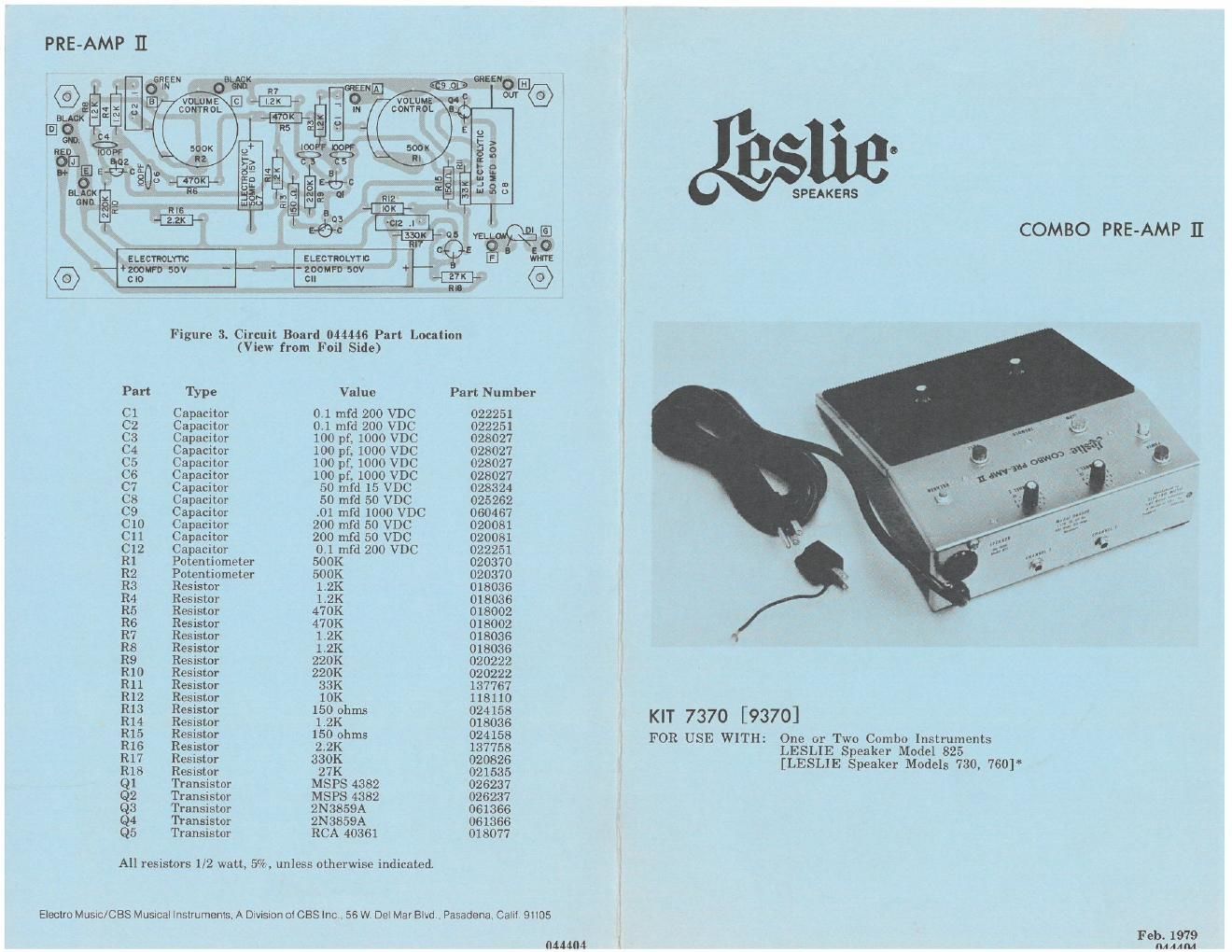
Figure 3. Circuit Board 044446 Part Location
(View from Foil Side)
Part Type Value Part Number
C1 Capacitor 0.1 mfd 200 VDC 022251
C2 Capacitor 01 mfd 200 VDC 022251
C3 Capacitor 100 pf, 1000 VDC 028027
C4 Capacitor 100 pf, 1000 VDC 028027
C5 Capacitor 100 pfi 1000 VDC 028027
C6 Capacitor 100 pf, 1000 VDC 028027
C7 Capacitor 50 mid 15 VDC 028324
C8 Capacitor 50 mfd 50 VDC 025262
CB Capacitor .01 mfd 1000 VDC 060467
C10 Capacitor 200 mfd 50 VDC 020081
C11 Capacitor 200 mfd 50 VDC 020081
CIZ Capacitor 041 mfd 200 VDC 022251
R1 Potentiometer 500K 020370
R2 Potentiometer 500K 020370
R3 Resistor 1.2K 018036
R4 Resistor 1,2K 018036
R5 Resistor 470K 018002
R6 Resistor 470K 018002
R7 Resistor 1.2K 018036
R8 Resistor 1.2K 018036
R9 Resistor 220K 020222
R10 Resistor 220K 020222
R11 Resistor 33K 137767
£12 gesistor 10K 118110
13 esistor 150 ohms 024158
R14 Resistor 1.2K 018036 KIT 7370 [9370]
R15 Resistor 150 ohms 024158 FOR USE WITH: One or Two Combo Instruments
R17 £9555? 323% éggggg LESLIE Speaker Model 825 *
esrs or LESLI
R18 Resistor 27K 021535 [ E speaker MOdels 730 760]
Q1 Transistor MSPS 4382 026237
Q2 Transistor MSPS 4382 026237
Q3 Transistor 2N3859A 061366
Q4 Transistor 2N3859A 061366
Q5 Transistor RCA 40361 018077

All resistors 1/2 watt, 5%, unless otherwise indicated.

Electro Music/CBS Musmal Instruments A DMSIOH 01 CBS Inc. 56 w De\ Mar Blvd , Pasadena Cali! 91105

Feb. 1979
"44404 M MM

Page 2

INTRODUCTION

The Combo Pre.amp II is designed to amplify and enhance the output from
one or two sound sources, such as a combo organ and guitar (or a combo organ
with two outrfut channels). Two input channels, each with its own jack and
volume control, are provided, Either can be used alone.

The power switch is located near the upper left corner of the pre-amp
chassis (figure 2). It controls power to both the pro-amp and the LESLIE
speaker. Power to the instrument attached to the pre-amp must be controlled
at the instrument itself.

The small red button identified as BREAKER restores pre-amp operation
in the event of a temporary overload. The circuit breaker acts like a fuse, to
protect the circuitry. Do not reset the circuit breaker after an overload until the
cause of the trouble has been found and corrected.

The two foot»operated switches on the rubber pad control the speed of the
tremolo rotors in the LESLIE speaker, The SLOW switch (left) selects between
slow (Chorale) and off. The FAST (right) switch selects between fast (tremolo)
speed and the operation for which the SLOW switch is set.

To alternate between slow and fast tremolo, first press the SLOW switch
until the corresponding indicator (amber) comes on. Once the SLOW switch is
actuated, pressing the FAST switch on or off varies the speed between slow
and fast. To stop the tremolo completely, press the SLOW switch until the
amber indicator goes out; then press the FAST switch to off (the red indicator
goes out).

KIT CONTENTS
Jfl M
044370 Combo Pro-amp Assembly, 117-V, 50/60-Hz -
Combo Pro-amp Assembly, 220/240-V, 50/60-Hz 044388

OZEOO Cable Assembly, 9-conductor (lilo-ft) 021600
034777 Adapter, power cable, 117-V -
053025 Oiler 053025
INSTALLATION
- CAUTION -

Due to the presence of electrical potential and the danger of moving
mechanical parts, installation procedures or adjustments requiring
Work inside the LESLIE speaker cabinet or the organ console should
be performed ONLY BY a service man authorized by the dealer
or factory to perform such work.

(NOTE: Locate the pre-amp where the musician can easily reach it with his foot.)
1. Connect the cable from the instrument to the CHANNEL 1 or CHANNEL 2
Jack at the rear of the preamp.
2. Prepare the LESLIE speaker as described in its own manual,

3. Plug the cable from the LESLIE speaker into the SPEAKER socket on the
combo pre-amp.

4. Connect the line cord to an AC outlet of the proper voltage.

5. Push the POWER on»off switch until the pilot lamp lights, indicating that
the pro-amp is turned on.

6. Press the SLOW foot switch until the amber indicator lights.

7. Press the FAST foot switch for fast or slow tremolo as desired.

8. At the LESLIE speaker amplifier set the volume control fully counter-

clockwise; then move it clockwise for about 1/3 of the total rotation.

9. Play a loud chord on the instrument and, while doing 50, increase the volume
of channels 1 and 2 of the pre-amp until distortion is heard. Then reduce the
pre-amp volume by about one and a half numbers.

10. While playing the same chord, slowly increase the volume at the LESLIE
speaker until distortion is heard. Then reduce the volume until distortion
disappears.

Installation is now complete.

*220/240V model

Figure 1. Combo Preamp II Schematic

PARTS LIST: COMBO PRE-AMP ASSEMBLY

044370 0442388"
044446 Circuit Board Assembly 044446
044511 Socket Assembly 044511
039636 Cable with Plug,r 129950
039594 Cover 039594
014720 Pilot Light, red (PLI, PL3) 014738
023085 Pilot Light, amber (PL2) 023077
039602 Phone Jack (J1, J2) 039602
020560 Circuit Breaker (CB1) 020560
026435 Switch, SPST, pushbutton (SW1) 026435
039610 Switch, DPDT, pushbutton (SW2, SW3) 039610
020354 Knob 020354
044230 Rubber Cover, 6-3/4 x 9-1/2 044230

GUARANTEE: One year from date of purchase, as stated on the guarantee card.

POWER ,
rsw l) V . g . Assv

,. . POWER

WDICAYOR sw I

LlGHT
(FEDiIFLll

CHNWEU cmmeu
wow JACK VOLUME

CHANNEL 2 CNANNEL 2 comm
PEAKED? VOLUME wow JACK

NPUT 50mm CONTROL

Figure 2. Part Identification