Leslie 7022 connector kit service manual

This is the 6 pages manual for leslie 7022 connector kit service manual.
Read or download the pdf for free. If you want to contribute, please mail your pdfs to info@audioservicemanuals.com.

Page: 1 / 6
left right
leslie 7022 connector kit service manual

Extracted text from leslie 7022 connector kit service manual (Ocr-read)


Page 1

CONSOLE CONNECTOR KIT 7022
INSTALLATION INSTRUCTIONS

FOR USE WITH; Pianos providing an output signal of less than 1.5 volts
LESLIE Speaker Set Model 60

KIT CONTENT


Control Assembly 112670
Screw, sheet metal, 8 x 3/4, 012476
E. Phillips head (2)
In 0 Installation Instructions 113120
fan
3: " ° 3
Sg-Qa .1.
0 a: 5 & CONNECIIOK TO PIANO 7\
u w ~21 W
a 5 509% CONNECTlON TO CABiNET/
I "=l~«- fil.__:::j
Sung?
0:
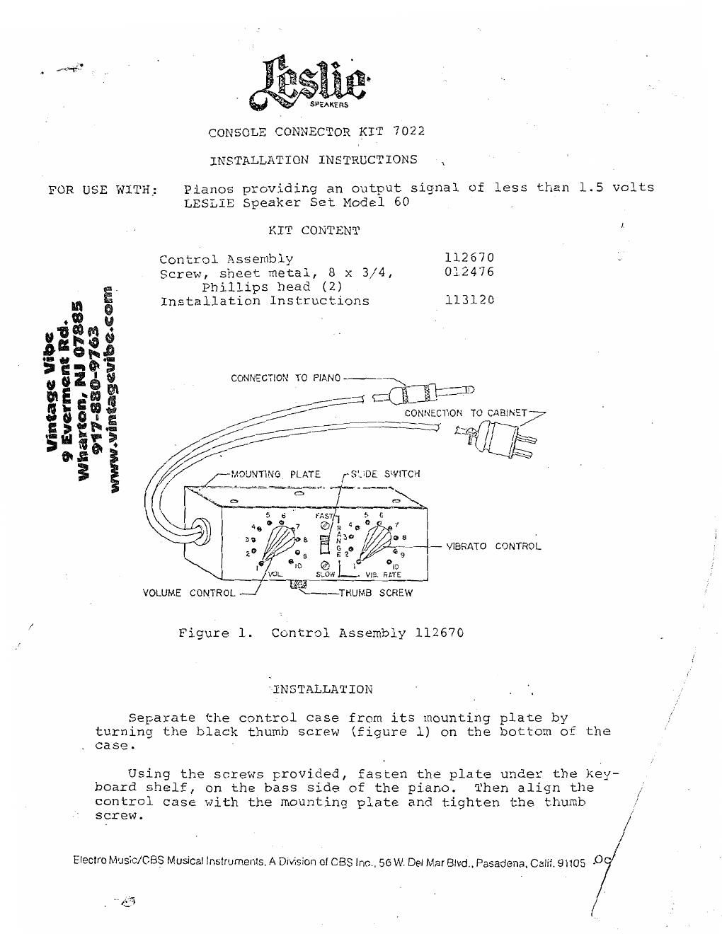
3 MOUNTING PLATE [-9.205 SWITCH

- ViBRATO CONTROL

VOLUME CONTROL F~THUMB SCREW

Figure 1 Control Assembly 112670

INSTALLATION

Separate the control case from its mounting plate by

turning the black thumb screw (figure 1) on the bottom of the
case.

Using the screws provided, fasten the plate under the key-
board shelf, on the bass side of the piano. Then align the

control case with the mounting plate and tighten the thumb ll"
screw. /

Eleclro Music/CBS Musical instruments. A Division of CBS Inc.. 56 Wt Del Mar Blvd Pasadena Calif. 91105 -O

If}

Page 2

gnu Mn

Two leads come from the control unit. One wire is long
and it terminates in a 5-prong plug. Insert this plug into
the INPUT socket on the back of the main speaker cabinet
(figure 2). Plug the short lead from the control units into
the earphone jack on the piano.

Prepare the LESLIE Speaker System Model 60 for operation
as described in the owner's manual or service manual.

N] 078854
0-9763

em: Rd.
W: ww.vintagevibe.c@

SIGNAL INPUT FROM
CONTROL UNIT

"tag: vibe

Evcrm

.
l

CONNECTIONS FOR -
SECOND SPEAKER SET?

V
917-88

9
Wharton,

CONNECTION
SATELLITE CAB 7

POWER IND2CATOR-

POWER SWITCH

FUSE HOLDER

POWER CORD

CORD
STORAGE AREA

Figure 2. Rear of Main Cabinet, Showing Connections

SOUND CONTROL

On the control case are two knobs and a slide switch. The
left-hand knob controls the volume of the output. The other two
items control the vibrato. The slide switch selects a range,
either FAST or SLOW, and the knob setting determines the amount
of vibrato within the limits of the range selected. Turning
either knob completely counter-clockwise sets the control to its
off position. The farther clockwise the knob is turned the
greater the volume or the greater the rate of tremolo which the
system will produce.