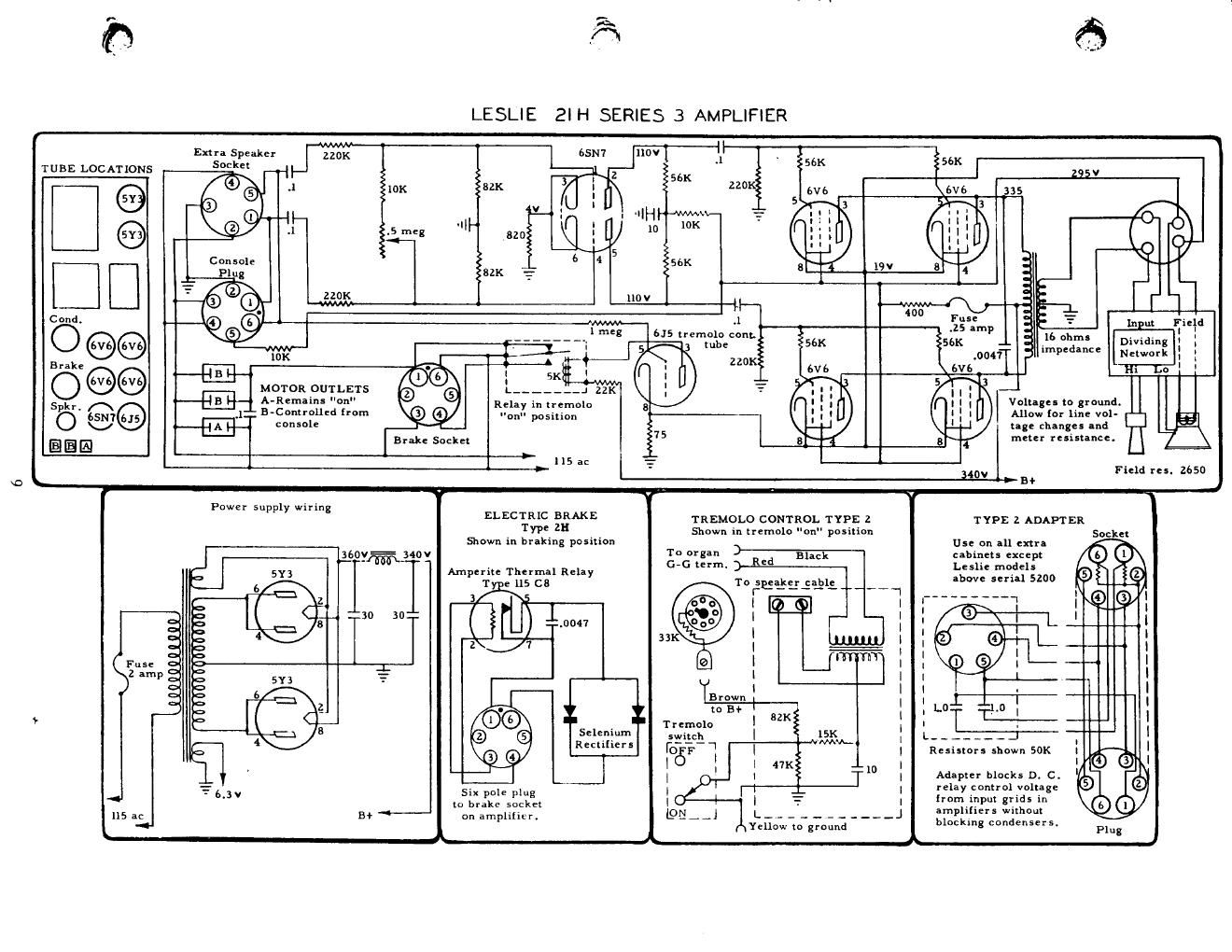
Leslie 21h series 3 schematics

This is the 1 pages manual for leslie 21h series 3 schematics.
Read or download the pdf for free. If you want to contribute, please mail your pdfs to info@audioservicemanuals.com.

Page: 1 / 1
left
leslie 21h series 3 schematics

Extracted text from leslie 21h series 3 schematics (Ocr-read)


Page 1

IL .
Extra Speaker 220K 0" I 11' ' 6
TUBE LOCATIONS 5mm 55x 5 K
EXOK 22° svb
5 3
.I|H w- ; = g :
10 10K ,; ,
. | >
t . U
56K 5
220g I
T l I
.1 Input liield
6J5 tremolo cont. . l .
lube 56K _o .16 3 Dlvldlng : ;
220 "le 3" Network I g
H: 50 l :

MOTOR OUTLETS
A-Remain! "on"

Relay in tremolo

8 Volt-gel to ground.
_ B ccnsole tag: changes and
Brake Socket 75 meter resistance.
1 15 ac _-L
l T Field res. 2650
B!»
+ _

Powe r supply wiring

#-

ELECTRIC BRAKE
Type 211
Shown in braking posiuon

Amperite Thermal Relay

211.0047
2\ 7
®.@ Selenium
e 9 Reed: r s
6 0

Six pole plug
to brake socket
on amplifier.

L

T j
TREMOLO CONTROL TYPE 2

Shown in tremolo on" posmon


To organ
G-G term.

10 lees-335931;

GE

I
|
l
I
I
l

I
Brown
to 3+

Tremolo
switch

r'-1
'06? 2
|

Yellow m ground

7

TYPE 2 ADAPT ER

Socket
Us: on all extra

cabinets except 6 l
Lzslie models
above serial 5200 5 Z

i__-\ £2 9

Resistors shown 50K

l

I
l
I
Adipler blocks D. c. '
relay control voltage
[rem input grids in

amplifiers without

bloclung condensers.