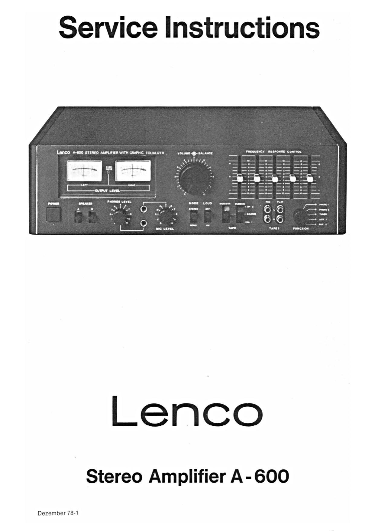
Lenco A 600 Service Manual

This is the 12 pages manual for Lenco A 600 Service Manual.
Read or download the pdf for free. If you want to contribute, please mail your pdfs to info@audioservicemanuals.com.

Page: 1 / 12
left right
Lenco A 600 Service Manual

Extracted text from Lenco A 600 Service Manual (Ocr-read)


Page 1

Service Instructions

33:53

Inn
I11!
IIII

Lenco

Stereo Amplifier A - 600

Dezember 78-1

Page 2

Specifications

Continous Power Output 2X52 W, 8 9 Signal to Noise Ratio (Din weighted)
2X66 W. 4 Q - Phono 58 dB
Total Harmonic Distortion at 1 W 0.05 /a - Mic 55 dB
Power Bandwidth 20-25000 Hz - Aux 60 dB
Frequency Response 10-40000 Hz Input Overload. Phono 150 mV
Damping Factor 60 Tone Control (Graphic Equalizer) 40 Hz
Input Sensitivity 250 Hz
- Phono 2 mV, 47 kg 1 kHz :10 dB
- Mic 2.5 mV. 47 kg 5 kHz
- Aux 150 mV, 470 k9 15 kHz
- Tape 150 mV. 470 k9 Loudness 100 Hz +6 dB
Crosstalk 60dB ( 1 kHz) 10 Hz +4 dB
50 dB (10 kHz) Dimensions 462x130X325 mm
(L X H X B)
Weight 13.3 kg (approx)

Level Meter Alignments
1. Set the Function Switch to Aux. 5. Increase the Volume Control Until Output Voltage 21.9 V.
2. Connect Audio Generator to Aux input. 6. Adjust VR 840 (RC. Board. S 1315 B) so that the output VU
3. Set the Audio Generator to Aux input. Meter indicates 60 W.
4. Connect AC Voltmeter at Speaker Terminal. 7. Repeat 1.. 2.. 3.. 4,. 5. Steps tor the other Channel.
Description of Exploded View
Rot. No. Parts Name Part No. Hot. No. Parts Name Part No.

1 Knob Power Push 22-555 25 Bracket Master (Front) 32-170

2 Knob Lever 22-553 26 Bracket Heat Sink (R) 232-181

3 Knob Balance 22-556 B 27 Bracket Heat Sink (L) 82-182

4 Volume 22-556 A 28 Bracket Master (Back) 32-171

5 Control 22-552 29 Bracket Side (L) 32-168

6 Slide 22-554 30 Gap Filler 33-016

7 Front Panel 20-036 31 Side Panel (R.L.) 20-033

8 Lens 40-229 32 P.C.B. S 1314 A

9 Meter Plate 30-015 33 Heat Sink 80-320
10 VU Meter 51-829 34 Bracket Heat Sink M.T.G. (R.L.) 32-213
11 Bracket Mic and Headphone Jack 32-180 A 35 P.C.B. S 1316 C
12 R.C.A. Connector 51-212 36 P.C.B. S 1316A
13 LED 3, Red 51-708 37 Top Cover 13-029
14 P.C.B. S 1314 C 38 Power Transformer 72-025
15 Front Chassis 10-028 39 Bracket P.C.B. 32-178
16 Power Push Switch 52-032 40 R.C.A. Connector 8 P 51 -209
17 Lamp 6.3 V, 220 mA 52-703 41 Push Holder Panel Screw Type 50-412
18 Lamp Grommet 40-401 42 Speaker Terminal 52-001
19 Bracket Lever X2 32-177 43 Kema Plug and Cord 61-301
20 Bracket Lever X4 32-176 44 Cord Stopper SR-4N-4 60-301
21 P.C.B. S 1316 B 45 Back Chassis 12-038
22 P.C.B. S 1315 B 46 Bottom Cover 13-030
23 P.C.B. 81315 A
24 Bracket Stittener (R) 32-211

Bracket Side (R) 152-167

Before disassembling. switch the unit off and disconnect the mains cable.