Leak varislope stereo owners manual

This is the 5 pages manual for leak varislope stereo owners manual.
Read or download the pdf for free. If you want to contribute, please mail your pdfs to info@audioservicemanuals.com.

Page: 1 / 5
left right
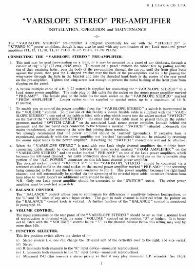
leak varislope stereo owners manual

Extracted text from leak varislope stereo owners manual (Ocr-read)


Page 1

H. I. LEAK 6t CO. LTD.

VARISLOPE STEREO PRE-AMPLIFIER

INSTALLATION, OPERATION and MAINTENANCE

_o-

The VARISLOPE STEREO pre-amplifier is designed specifically for use with the STEREO 20 or
STEREO 50 " power amplifiers. though it may also be used with any combination of two Leak monaural power
amplifiers (TL/12. TL/IO. TL/IZ PLUS. TL/25 PLUS. TL/SO PLUS).

CONNECTING THE VARISLOPE STEREO PRE-AMPLIFIER.

1.

This unit may be used free-standing on a table. or it may be mounted on a panel of any thickness. through a
cut-out of mi x 3} (27 cms. x9-85 ems.) To mount on a panel: remove the rubber feet by pulling smartly
out of their retaining holes: pass the body of the pre-amplifier through the cut-out until the front plate butts
against the panel. then pass the U-shaped bracket over the back of the pre-amplifier and fix it by passing the
wing-screw through the hole in the bracket and into the threaded hank-bush in the centre of the rear panel
on the pre-amplifier. Tighten the wingAscrew just enough to prevent the metal backing of the front plate from
slipping on the panel.

A brown multiple cable of 4 ft. (122 metres) is supplied for connecting the VARISLOPE STEREO" to a
Leak stereo power amplifier. The male plug on this cable fits the socket on the stereo power amplifier marked
PRE~AMP . The female plug on the cable fits the male socket on the VARISLOPE STEREO marked
FROM AMPLIFIER ". Longer cables can be supplied to special order. up to a maximum of 16 ft.
(5 metres).

To enable you to control the power amplifier front the VARISLOPE STEREO " a switch is incorporated in
the VOLUME " control. To make use of this facility a 2-core flexible cable is supplied with the VARI-
SLOPE STEREO : one end of the cable is fitted with a plug which inserts into the socket marked SWITCH
on the rear of the VARISLOPE STEREO " : the other end of the cable must be passed through the rubber
grommet marked SWITCH CABLE" on the associated Leak stereo power amplifier, knotted behind the
grommet. and the two bared ends connected to the terminals marked SWITCH " (situated underneath the
mains transformer), after removing the wire link ioining these terminals.

We strongly recommend that the power amplifier should be earthed (grounded). If excessive hum is
experienced. particularly with the power amplifier not earthed' (grounded) this can be reduced by reversing
the mains input leads to the power amplifier. Reversing the SWITCH connections will not be effective.

When the VARISLOPE STEREO " is used with two Leak single channel amplifiers the multiple inter-
connecting cable should be connected between the male socket marked FROM AMPLIFIER" on the
VARISLOPE STEREO " and the socket marked PRE-AMP " on one of the Leak power amplifiers. which
becomes the left-hand channel. An earth connection should be taken to the third pin on the removable plug
portion of the AC. POWER connector on this left-hand channel power amplifier.

The co-axial socket marked OUTPUT R" on the VARISLOPE STEREO" should be connected via a
screened co-axial cable to the octal socket on the second power amplifier marked PRE-AMP ; the screening
being connected to Pin 1 and the live inner conductor to Pin 8. This power amplifier becomes the right-hand
channel. and will automatically be earthed via the screening of its co-axial input cable ; to ensure freedom from
hum (due to earth loops) no additional earth should be made.

N.B.-Only one Leak power amplifier should be connected to the SWITCH " socket. The other power
amplifier must be switched separately.

BALANCE CONTROL

The BALANCE control allows you to compensate for diflerences in sensitivity between loudspeakers. or
the L and R sides of any stereo input device. The gain in each channel is identical when the pointer on
the BALANCE " control knob is vertical. A further function of the BALANCE control is mentioned
in paragraph 16.

VOLUME CONTROL.

The input attenuators on the rear panel of the VARISLOPE STEREO should be set so that a normal level
of reproduction is obtained with the main VOLUME " control set to position 3 or higher. It is better
not to listen with the VOLUME control below 3". as the channel balance below this setting may vary by
more than ldb.

FUNCTION SELECTOR.

This five position switch allows the choice of :-

(i) Stereo reverse (i.e. one can change the left-hand side of the orchestra over to the right. and vice versa).
(ii) Stereo.

(iii) R (connects both channels to the R input device-monaural reproduction).

(iv) L (connects both channels to the L' input device monaural reproduction).

(1:) Monaural P-U (this converts a stereo pickup so that it may play monaural LP. records). See ll(d).

Page 2

8. PICKUP SELECTOR.

This two position switch permits you to select either of two stereo pickups or. when used in conjunction with
the function switch. two monaural pickups and one stereo pickup. or four monaural pickups.

9. HUM.

The VARISLOIE STEREO" pre-amplifier has an extraordinarily low hum level. which can be checked by
removing the input plugs and turning up the VOLUME " control. The connection of any input device to
the input sockets will lower the input impedance and should, therefore. reduce the hum level. If the hum
level increases on making these connections. the cause of the hum must lie outside the pre-amplifier. and our
instructions on the connection of the varying input devices should be read carefully in an attempt to locate the
cause of the hum.

IO. HISS.
With the input control switch to MIC" TAPE". or PICKUP and the VOLUME" control at
maximum, a certain amount of hiss will be heard. This hiss is as low as is possible to obtain at the present
date. and it is inherent in high-gain vacuum-tube amplifiers.

ll. CONNECTING STEREO PICKUPS.

(a) The greatest care has been taken in the design of this pre-amplifier to ensure that any pickup generally
available in the world can be connected to give optimum results, i.e. the highest quality obtainable from
the chosen make of pickup. Our prime aim is for you to obtain optimum results from the pickup of
your choice.

(D) The pickup should be connected via screened co-axial cables to the sockets marked PICKUP at the
rear of the VARISLOPE STEREO " pre-amplifier. as shown below.

THE INS! WIRE

-*- TAKENTNFIOUGH
HOLLOW CENTRE PINS
_ . / ' "R" /AND SOLDERED AT
4' fit

__________________ THE TIPS

PICKUP

SNORTEST POSSBLE LENGTNS SCREENING SOLDERED
OF UNSCMMD WIRES T0 OUTER SHELLS PICKUP INPUT PLUGS

(c) Some pickups will be fitted with two inner conductors covered by one outer screening: in this case the
user should make sure that the screening of both inner conductors is maintained right up to the plugs
fitting the sockets marked PICKUP ", as shown below.

.. ______________________ T/W- '-


' r : 3-7HE INNEFI WIRES
PICKUP , TAKEN THROUGH
l ________________ NOLLW CENTRE PINS
/ mo SOLDERED AT
1-: TIPS

SHOMEST POSSIBLE LENGTMS
OF UNKREENED WIRES SCREENth SOLDERED
TO OUTER SHELLS PICKUP INPUT PLUGS

((l) The majority of stereo pickups are suitable for reproducing from monaural records when the two pickup
outputs are short-circuited : the FUNCTION " switch on the pre-amplifier effects this short-circuit when
turned to MONAURAL P-U
Some pickups do not conform to this convention and have a separate monaural (or lateral) output. When
using this type of pickup the stereo outputs should be connected to the input sockets of PICKUP l and the
monaural output to the input socket marked R on PICKUP 2. For the reproduction of stereo records.
the pickup selector should be turned to PICKUP l and the function switch to STEREO". For the
reproduction of monaural records the pickup selector should be turned to PICKUP 2 and the function
switch to R .

(e) We know from experience that the main troubles encountered by the music-lover at home are with the
reproduction of records. There are five major reasons for these troubles :-

(i) No record can possibly give perfect reproduction. and many records (perhaps the majority) contain
noticeable distortions due to imperfections in recording and/or processing. These imperfections may
show up as rattle , high surface noise. recorded hum and rumble. and recorded wow . Shrill
treble may be due to a poor record, and/or due to a pickup having its high-frequency resonance
within the audible range.

(ii) No pickup is perfect and the majority have performances very much below those which are attainable.

2