Leak tl 50 plus service manual

This is the 4 pages manual for leak tl 50 plus service manual.
Read or download the pdf for free. If you want to contribute, please mail your pdfs to info@audioservicemanuals.com.

Page: 1 / 4
left right
leak tl 50 plus service manual

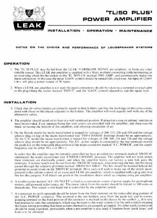
Extracted text from leak tl 50 plus service manual (Ocr-read)


Page 1

'TL! 50 PLUS'
POWER AMPLIFIER

INBTALLATIDN ' DFEHATIDN ' MAINTINANCI

NOT!- ON THE cHDIcl AND leFanMANcl as LDUDIBIAKIH IVIYIMI

DFERATIDN

l. The TL 50 PLUS may be fed from the LtAK wwmswre moxo Ilre-.impllllcr. or from dn) um

. When u LEAK preamplifier is no! used the lnpul cunnecllum xliuuld he lake on a wreened e0 - uul

\uildhlc source. This LEAK pre-umplillcr is \llppllfll With .i hl.i L multiple eonnecimg euhle lermin.iiing in
an oclzil plug which fits [he sockcl nii Ilie 'TI 54) PLUS' mzirlcd PRl'vMP'. .ind :iulnmuticzllly ln:ike~ IItc
input connection. lnlliisczneilic input '(iAlNeontrol \hould be Iurned full) clockwise, \f| inpul of IISmV
r.m,). I give a power oulpul of 50 watts.

III:
In the plug liiiing ihe socket marked IMLT'. and the (iAIN eonirol lldlllsltd to SUII the signal lctel.

INSTALLATION

.l.

(I,

Check that all valves Iiuhes) are correcily sealed in iheir holden :ind th.ii the markingsun the NM) corres-
pond with those on the chm s uilJuLenl In llle holders The umplillei will work equally well wi 1|") nl'the
aliernuiile \uhcs.

The nmplilicr should \lilnd on II\ him: in 1i nell-venliluled pthlllun. Ilpl.iced in :i use or ezibinei. Ienlilzilinn
mu~i he provided. lour \cpurulc litiiig lcel mih \cmm iive prmided uiih ihe amplifier. and Iliese muu be
filled. so ruising the boltom of the umplilier, :ind ulIiMmg circuliilinn nt'uir.

. 0n the Hrilinh model the milll'h lrunsl'ulmc! Is upped for \ulldges of 300. 213. 326 and 239 and the mluge

welcclor plug on lop ol' Ihe mill! traimformer (we 'IOP (HASSIS dram-nit) ~hould he wi uppropnai
On the U 5. model lhe mill": traiinl'urmer is tapped for voliugh nl IOO. IIIX. III! and IM and III: Inllnge
\eIecior plug )IIUUILI he set appropriately, lhe A.(, power \upply is connected In Ilie Iwo terminal: ncurcsl
the guide Le). on [he removable plug purliun ni'ihe mums cunnctlur marked 'A (2 POWER. and the \upply
frequene can be either 50 e s or (>0 c \

In order that Ihe :implilicr may be remotely controlled me fine Pi'oiided luo terminals murked 'SWI K ll'
llndernculh Ihc mums Irziml'urmer (we UNDER CHASSIS" Alumina). The :impllllel' Mill rim work unless
these terminals .ire eleclrtuill) Joined .ind when the AIIVIPIIIICI leu \ our lliulory 4 wire III'III JON Ihe
terminals A rcmoicx 'ieh "It be run from Ihc' VI"II(' ll ICYITIIIIJK :il'icr rcmmingihe link. the flex hemg
puma lhrnugh lhc.|tl|1lccnl grnmmel marked swm ll ( ABLL IIIC flu ~huii|d he knotted behind the
grommcl to .nold \Iniin on the SWI l'('|l' Itlmllhlh Mml uIcrI \Iill MHII to make use ol the much incor-
named in ihe mlume cunlrnl ol. .moeiuted l.l-' AK pienimplillcr. VIIIILII l\ \upplicd Inih :- plug .ind ivun
flu l'nr um purpw Full den-h :irc gncn .n ma .muiuuon \hcch which accompany cmy preamplifier.

A dimple meLcI marked A.(' ()l' l Ll; I S" n titled in .i cmiIeiticht \iiilrcc ol power euppl) l'nr grumnphon:
mouth. scllvptmcred radio iuiien. cic The pnuer LiIcn from ilin snkkel \hnuld be limited to lot) mm». or
ihermhouis. I'hn \oeIet IV iini lmcd but I\ cnntrolled by the .implitier sullkh

. A connection In earth (ground) should he taken from ilie iliinl icrmin.il nn the remomhle plug. portion of

the A L. PUWLR connector "I icrnnmil l\ ihe one I'urihesi JIM!) from Ihi. guide key iind II: surrey
puiiding ierminul on ilie lilcd ponion olihe uonneeior n marked on ihe chums by ihe xanbUIA- unit IS very
bad [InlClICC in omit lhlsctInncCliLln. which may be nude io ihc uuier snicm or in ihe \teel eondiiil encasing
the house Wiring prowling that these syslems Ihcmvclvex are properly grnunded, No oiher earth eonneciiuns
ahuuld be made elxwhere. particularly when ii [Ire-amplifier is also used. if freedom from 'eurth loop; and
hum I) to be ubluined,

Page 2

X. The loudspeaker shtiultl be connected by a "mini! pair of wires to the plug marked LOUDSPEAKFR. It
will be seen from the circuit drawing that one side orthe loudspeaker winding is connected to the chest nd
no part of the loudspeaker wiring should be earthed elsewhere. The DC resistance of the connectmgwnes
should be as low as possible. and not more than one practice to operate any power amplifier without a loudspeaker. an s desired to mate the Ioudspeakerhy
switching it out of circuit this should be accomplished by use of a change-over swnch which replaces it with
a resistor ofcorresponding value and rating. The selector plug on top of the output transformerlsec TOP
CHASSIS drawing) should be adjusted for the nearest match to the advertised Impedance of the loud-
speaker.

GENERAL NOTES ON MAINTENANCE

The circuit din :im provides it qu
following points may he oi'intcmt;

lied engineer with all information required for servicing However. the

tui The TL 50 PLUS' does not depend upon the output valves (tubes) being a matched pair Io give lilc stated
performance. and if one output Valve fails it is not nece try to repltitx: both.

(hi Should it ever be necessary to replace the reservoir capacitor CM note that ii must he ofa type capable of
handling at least 20llmA ripple current. The ('I4 titted has a high margin of safety. being capable of handling
240mA.

NOTES ON LOUDBPEAKEH BYITEMB
Space does not allow for detailed explanation on this vtisl subject. but the following points should be noted :7

(a) This amplilier will operate any high fidelity loudspcalter system. both movingcoil and electrostatic types.
including the small low sensitivity assemblies currently popular. particularly in the USA.

(It) You cannot get high lidelity results if ytiu mount a loudspeaker in the same cabinet as the turntable and
pickup.

it)

. mhly commonly called a 'Iouilspeaker consists of a magnet. is moving-coil and a diaphragm (or
cone . T ' assembly i motor. Von do nul listen to a motor; you listen to a loudspeaker system. which
consists of one or more noton mounted in it housing (baflle. box. cabinet. or horn). The housing plays a
profound part in determining the q y of reproduction. The efl'ecls of various housings are discussed by
l.. l . Heranelt in At'tiiulirr. Mt:(ir;i ill Publishing Co Ltd. First Edition.

(z/i One good motor. properly housed. is capable ofg ing irly good results. but two good motors. properly
hullwdr oill give notice hly better results: in Ihls case one motor is designed to reproduce bass. and the
other treble. A litter (tliiiding nCIWork'l must he used iit conjunction with the two motors.

4t-

chiemhet that even the best content I loudspeaker systems are by far the aeukext link ti.e.. the greatest
source ttltlistortion) in: gh lidc L um and that such systems are relatively expensive. The fundamental
weaknesses of conventional loudspeaker» r dl\Lu\'\cli succinctly in ' paper by H J. Leak. High Fldl'll'lvl'
IJIIIIIAIHNIH'IX. The Ii'r/nriiiunt-t-nl .llurmui uiluml E tlnlaltllir Trim, mi'nJournal of the British Institute
of Radio Engineers. Vol. in. No. I3. lkccmbcr IQSh. Copies are: able from the Institution. 9 Redford
Sq rc. London. W.C.l. price 7 . Houmerr \uch systems we become out-modcd by the revolutionary
Leak ventinn of the composite \anduich diaphragm The basic principles are described by D. A. Barlow.
M. . (M d of the l. k Tl:lll\dll r Revs rch Department) in Win ix Il'mlrl. December l9.ll. A further
paper dcull 'ng the u niplcte l nilt 'Srintlttich loudspeaker system VHM delivered to the British Institution
of Radio Engineers b) Dr -\. Btirlovt and H J. Lctlk on the 24th January. I962. and will be p|lhli\hcd in a
forthcoming journal of the limitation.