Lafayette la 125ta supp en

This is the 2 pages manual for lafayette la 125ta supp en.
Read or download the pdf for free. If you want to contribute, please mail your pdfs to info@audioservicemanuals.com.

Page: 1 / 2
left right
lafayette la 125ta supp en

Extracted text from lafayette la 125ta supp en (Ocr-read)


Page 1

SUPPLEMENTARY INSTRUCTIONS

MICROPHONE/MUSICAL INSTRUMENT CONNECTION

The LA-TYPE may be connected to any high impedance dynamic microphone (50K S2 or above) or mu-
sical instrument pick-up. The MIC/MUSICAL input jack on the front panel of the amplifier mates

with a standard 1/4 inch 3-conductor phone plug such as a Lafayette type 99-6119. The phone plug
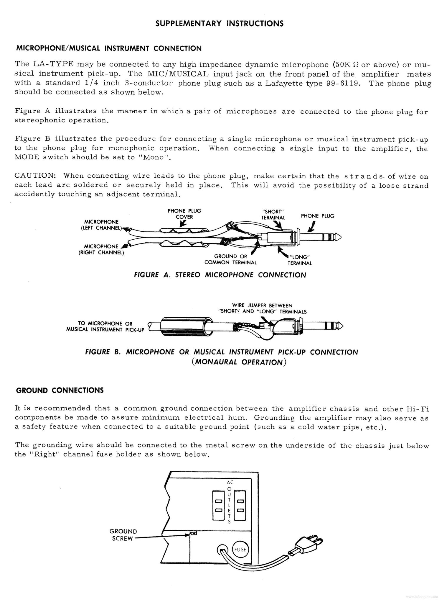
should be connected as shown below.

Figure A illustrates the manner in which a pair of micrOphones are connected to the phone plug for
stereOphonic operation.

Figure B illustrates the procedure for connecting a single microphone or musical instrument pick-up

to the phone plug for monophonic Operation. When connecting a single input to the amplifier, the
MODE switch should be set to "Mono".

CAUTION: When connecting wire leads to the phone plug, make certain that the s t rands. of wire on
each lead are soldered or securely held in place. This will avoid the possibility of a loose strand
accidently touching an adjacent terminal.

PHONE PLUG "SHORT"
COVER TERMINAL PHONE PLUG
MICROPHONE
(LEFT CHANNEL)


MICROPHONE

COMMON TERMINAL TERMINAL

FIGURE A. STEREO MICROPHONE CONNECTION

WIRE JUMPER BETWEEN
$HORT,~' AND LONG TERMINALS

TO MICROPHONE OR
MUSICAL INSTRUMENT PICK-UP

FIGURE 3.. MICROPHONE OR MUSICAL INSTRUMENT PICK-UP CONNECTION
(MONAURAL OPERATION)

GROUND CONNECTIONS

It is recommended that a common ground connection between the amplifier chassis and other l-li-Fi
components be made to assure minimum electrical hum. Grounding the amplifier may also serve as
a safety feature when connected to a suitable ground point (such as a cold water pipe, etc.).

The grounding wire should be connected to the metal screw on the underside of the chassis just below
the "Right" channel fuse holder as shown below.

GROUND
SCREW

Page 2

"COMPUTOR-MATIC" OVERLOAD PROTECTION"

(Replaces former "Protective Fuses")

This unit is equipped with a newly-developed overload pro-
tection circuit (patent pending) that eliminates any poss-
ibility of damage to drivers and output transistors caused
by momentary or sustained-overloads. A special 2-transistor
circuit is used in each channel that continuously monitors
the output transistor stages. Any abnormal condition is
immediately sensed and the protective circuit will act in-
stantly to cut off operation of the amplifier before damage
can result. Not only is this computer-type protective cir-
cuit hundreds of times faster than a fuse, but it is also
self-restoring. When the cause of overload is no longer
present, the circuit automatically begins to restabilize and
normal operation is generally resumed within 1 or 2 seconds.

HOW TO RECOGNIZE THE OPERATION
OF THE PROTECTIVE CIRCUIT

When anoverload occurs (even momentarily) the protective
circuit will operate instantly and the unit will be silenced.
If the overload has occurred only on one channel, only that
channel will be silenced. So long as the overload exists,
the unit will remain silent on one or both channels. As soon
as the cause of overload is removed, the circuits will begin
to re-stabilize and, after l or 2 seconds, the equipment will
resume normal operation.

On rare occasions, the unit may fail to recover from a severe
overload and remain silent even when the cause has been re-
moved. If this occurs, simply set the volume control fully
counter clockwise to minimum for 2 or 3 seconds, then return
it to its normal position. This action will speed the re-
stabilization of the circuits.

CAUSES OF OVERLOAD

Overloads can be brought about by a number of causes, either
momentary or permanent.

Momentary overloads can result from severe noise impulses such

as those caused by lightning and static, switching noise, or

from momentary shorting of speaker lines. Under these conditions,
the receiver will usually resume normal operation within 1 or

2 seconds. Permanent overloads will result if speaker lines

are permanently shorted or if a sustained signal of abnormally
high level is applied to theinput of the amplifier section

(such as excessive hum, for example). Permanent causes of
overload must be located and rectified before the unit canrre-

sume normal operation.

LAFAYETTE RADIO ELECTRONICS CORP.

Schd 31 8A