Lafayette he 29 a service manual

This is the 6 pages manual for lafayette he 29 a service manual.
Read or download the pdf for free. If you want to contribute, please mail your pdfs to info@audioservicemanuals.com.

Page: 1 / 6
left right
lafayette he 29 a service manual

Extracted text from lafayette he 29 a service manual (Ocr-read)


Page 1

LAFAYETTE

PHOTOFACTQ Folder wn- moon HE-29A


NOTICE

ONLY THOSE PERSONS PROPERLY LICENSED ARE

PERMITTED TO MAKE REPAIRS OR ADJUSTMENTS

WHICH MAY RESULT IN ILLEGAL OPERATION,

(REFER TO FCC RULES & REGULATIONS PART I9,
SUBPART D, SECTION 19.71,)

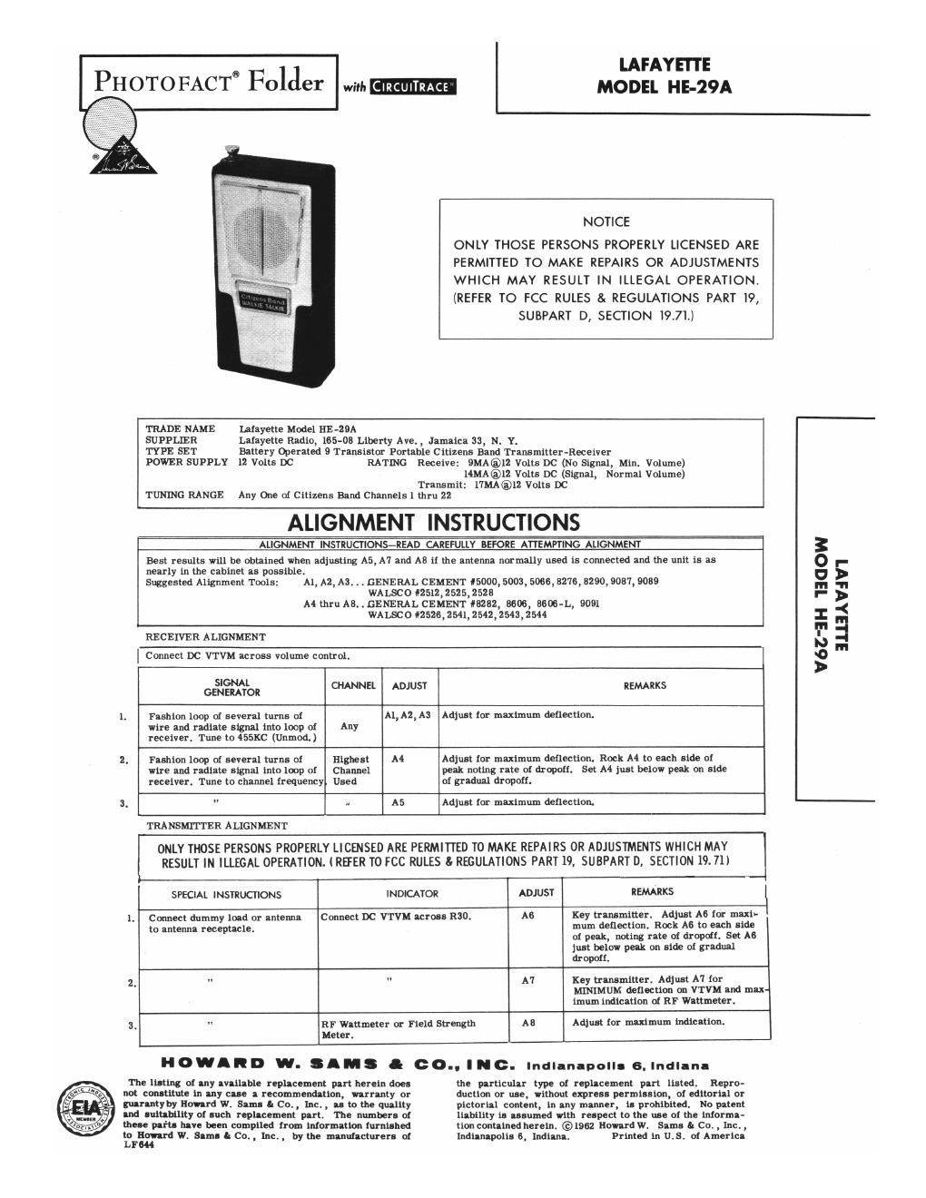
TRADE NAME leayette Model HE-29A

SUPPLIER Lafayette Radio, 165-08 Liberty Ave. , Jamaica 33, N. Y.
TYPE SET Battery Operated 9 Transistor Pol-table Citizens Band Transmitter-Receiver
POWER SUPPLY 12 Volts DC RATING Receive: 9MA®l2 Volts DC (No Signal, Mill. Volume)

14MA®12 Volts DC (Signal, Normal Volume)
Transmit: 17MA®12 Volts DC
TUNING RANGE Any One of Citizens Band Channels l mu 22

ALIGNMENT INSTRUCTIONS

ALIGNMENT INSTRUCTIONS-READ CAREFULLY BEFORE ATTEMPTING ALIGNMENT

Best results will be obtained when adjusting A5,A'l and AB it the antenna nnl'mally used is connected and the unit is as
nearly in the cabinet as possible.
Suggested Alignment Tmls: A1, A2, A3. . . GENERAL CEMENT 55000, 5003, 5066, 3270, 0290,9007,9009
WALSCO «2512, 2525, 2528
A4 thxll AB. . GENERAL CEMENT 8282, 3606, BEN-L, 9091
WALSCO «2526,2541,2542,2543, 2544

RECEIVER ALIGNMENT

Connect DC VTVM across volume control.

SIGNAL
GENHWOR CHANNEL ADJUST REMARKS
Fashion loop at several turns of Al,A2,Aa Adjust fnr maximum deflection.

wire and radiate signal into loop at Any
receiver. Tune to 455KC (Unmod)

2. Fashion loop of several turns of nglfist A4 Adjust Tor maximum deflection. Rock A4 tn each side of
wire and radiate signs! into loop of Channel peak noting rate 01 dropoii. Set A4 just below peak on side
receiver. Tune to channel frequency Used of gradual dropoif.
3. " n A5 Adjust for maximum deflection.
TRANSMITTER ALIGNMENT
ONLY THOSE PERSONS PROPERLY LICENSED ARE PERMITTED TO MAKE REPAIRS OR ADJUSTMENTS WHICH MAY
RESULT IN ILLEGAL OPERATION. IREER TO FCC RULES I: REGULATIONS PART 19, SUBPART D, SECTION 19. 71)
SPECIAL INSTRUCTIONS INDICATOR ADJUST REMARKS I
1. Connect dummy land or antenns Connect DC VTVM across R30. A6 Key transmitter. Adiust A6 [or maxi- I
to antenna receptule. mum deflection. Rock A5 to each side
oi peak, noting rate oi drown Set A6
just below pm on side at gradual
drops.

2. " " A7 Key transmitter. Adjust A7 [or
WNTMUM deflection an VTVM and max-
imum indication sf RF Wattlueter.

3. " RF Wattmeter 01' Field Strength A8 Adjust (or maximum indication.

Meter.
H o "A R D w. 3 M S l c 0.. I H c. Indlan-polls 8. Indlanl
The listing or my Ivliiable replacement part herein does the particular type oi replacement pnrt listed, Repro-
wot constitute in any cue a recommendation, urnnty or auction or use, without express permission, 9! editorial or
mrmtyby Haw-rd w. Sam- I: Co. , Inc. , u to the quality pictorial cantent, in any manner, is prohibited. No pstent
Ind Iuitnhility oi such replscement part. The numbers of liability is assumed with respect to the use at the inlet-mm
the" parts have been compiled from inlormation (ml-had lion conuined herein. @1962 Howard W. Sims 5 CO. , XIIC. ,
to sow-rd w. Slml a C0. , Tnci , by the mnnuuctursu at Indianapolis 6, Indians. printed in us. of Americl

LEM!

V6Z'3H TEGOW

BHIAVIVT

Page 2

YELESCOPI C ANTENNA

1:! Ir AMP 2ND IF MP .5;

6925sz
C


RECEIVE

,@
-IRA:I:MIE @
d

l

20mm

1? TP

I 4

u TERMINAL GUIDE Ll TERMINAL GUIDE

e v mm H

u TERMINAL GUIDE

IIc - I
T T T T T T
PUSHTOTALK
L L L J.
L: TERMINALGUIDE LT TERMINALGUIDE
RECEIVE
6 > 12
5 I]
to 019
3 9
Z 8
1.: I oz
WANSMIT

m TERMINAL GUIDE
(BOWOMVIEWI
SPRIm LOADED Tu
RECEIVE POSIYIW

3 FINAL AMP

.25AIo4

17-"
TEST Poms

@ won
L L
us TERMINAL GUIDE ._I_L_

ALL MEASUREMENTS "KEN III "RECEIVE" V05 IIION
wuss OTHERWISE DESIGNATEU.
- TAKEN IN "TRANSMII" POSITION.

RESISTANCE MEASUREMENTS NOT GIVEN EEEAUSE of THE
WIDE VARIATION IN INTEMAL TRANSISIUN RESISIANCE.

0 s5: run usr won ALTIINAYI
mm on muunou
I. nc wanna munmms um um mum» Tuba numr.
1 Such! mnmlmm «mum Ilrmlluli m shown x
mm vlews.
:. Plasmid values an mm m pm or min! In
mmlmn gmum.
1. mm Inlmm on mmmm values mm mm: a
mum u «Isv. In Von-g: m: mist-nu mums.
5. mm». mm m mulmum no sign: mum m wanna
"Insulin-ML
A movouct sunmw Nonuou scnmmc

mm

'nwavd w Sam cm In, 19a: