Lafayette he 20 b service manual

This is the 8 pages manual for lafayette he 20 b service manual.
Read or download the pdf for free. If you want to contribute, please mail your pdfs to info@audioservicemanuals.com.

Page: 1 / 8
left right
lafayette he 20 b service manual

Extracted text from lafayette he 20 b service manual (Ocr-read)


Page 1

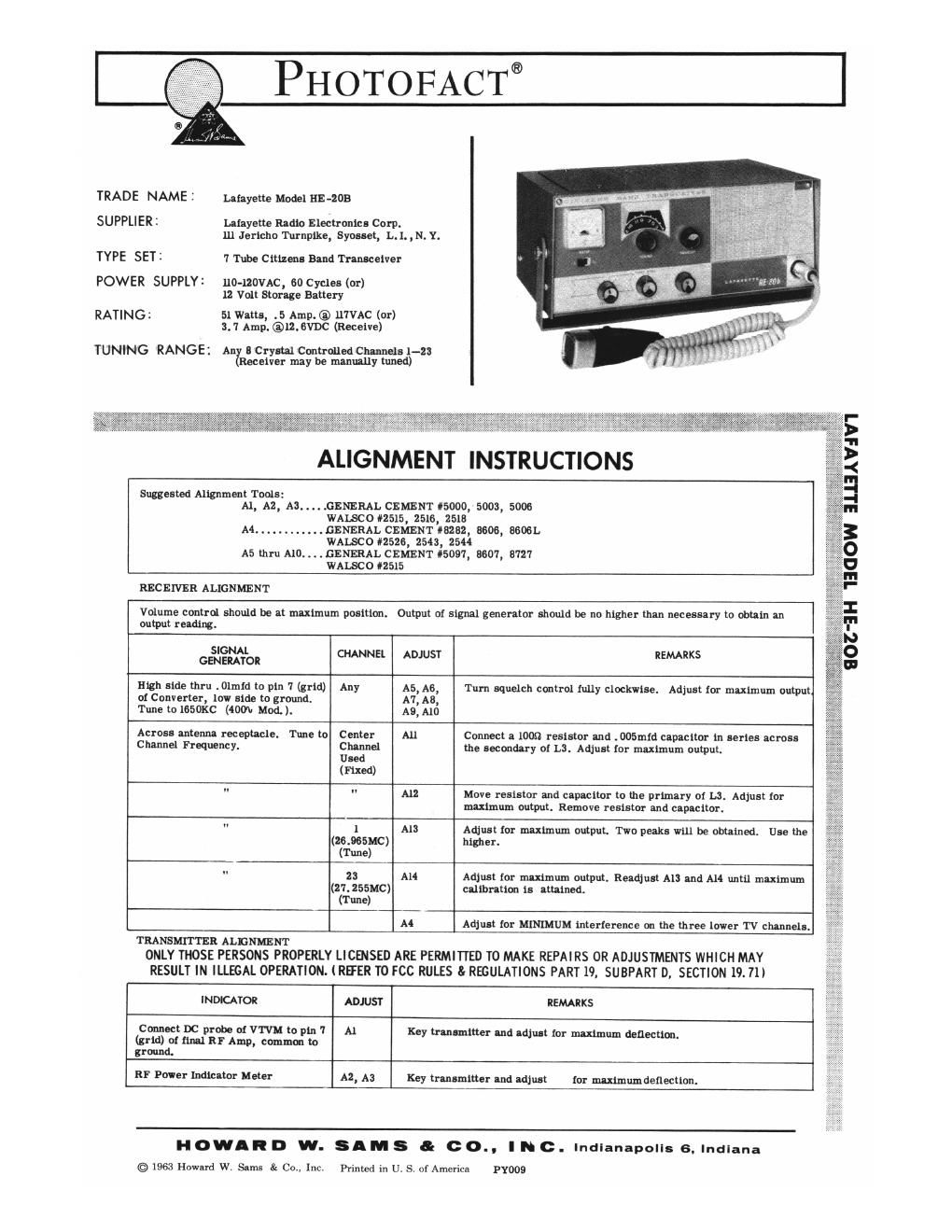
PHOTOFACT®

TRADE NAME : Lafayette Model n1: -zoe

SUPPLIER : Lafayette Radio Electronics Corp.
111 Jericho Turnpike, Syneset, L. l. ,N. Y.

TYPE SET 3 1 Tube Citizens Band Transceiver

POWER SUPPLY: llO-IROVAC, so Cycles (or)
12 Volt Storage Battery

RATING: 51 Watts, .5 Amp.® ll'1VAC (or)
3. '1 Amp. @12.8VDC (Receive)

TUNING RANGE: All 3 Crystal Controlled Channels 1-23
Receiver may be manually tuned)

ALIGNMENT INSTRUCTIONS

Suggested Alignment Tools:
Al, A2, A3 ..... G ENERAL CEMENT #5000, 5003, 5006
WAISCO #2515, 2516, 2513
A4 ............ GENERAL CEMENT #8282, 3606, 88061.
WALSCO #2526, 2543, 2544
A5 thru A10. . . . GENERAL CEMENT #5097, 8607, 8727
WALSCO 2515

RECEIVER ALIGNMENT

Volume control should be at maximum position. Output 01 signal generator should be no higher than necessary to obtain an
output reading.

SIGNAL REMARKS
GENERATOR CHANNEL ADJUST
High side thru . Olmid to pin 7 (grid) Any A5, A6, Turn squelch control fully clockwise. Adjust (or maximum output
01 Converter, low side to ground. A7, A8,
Tune to 165OKC (400W Mod. ). A9, A10
Across antenna receptacle. Tune to Center All Connect a loan resistor and . 005mid capacitor in series across
Channel Frequency. Chnnnel the secondary oi LS. Adjust ior maximum output.
Used
(Fixed)
" " All Move resistor and capacitor to the primary of LS. Adjust for
maximum output. Remove resistor and capacitor.
" 1 A13 Adjust for maximum output, Two peaks will be obtained. Use the
(25.965110) higher.
(Tune)
" 28 A14 Adjust for mudmum output. Readjust A13 and All until maximum
(27.255MC) calibration is attained.
(Tune)
A4 Adjust tor MINIMUM lnterierence an the three lower TV chunels.

TRANSMITTER ALENMENT
ONLY THOSE PERSONS PROPERLY LICENSED ARE PERMITTED TO MAKE REPAIRS 0R ADJUSTMENTS WHICH MAY
RESULT IN ILLEGAL OPERATION. (REFER TO FCC RULES 5: REGULATIONS PART 19. SUBPART D. SECTION 19. 71)

INDICATOR ADJUST REMARKS
Connect DC probe of VTVM to pin 7 A1 Key trenemitter and edju-t for nullmum deflectim.
(grid) at final RF Amp, comma: to
ground.
RF Power Indicator Meter A2, A3 Key transmitter and adjust (or maximumdeflectinn.

HOWARD VII. SAM S & co.. IN c. Indianapolis 6. Indlana
© 1963 Howard W. San-ls 8: Co. Inc. Printed in U. S. of America PY009

Page 2

@®®®®®®@®@®®@®®®®®®®
®
(ED
@
®
®
®
®
®
®
619 x w
a -- w w
QE®®®®®®C ®®<®®®®®®®

®®¢®MM®®®®®®®®®

@

®@®®®®®@®

m
63
®
®
®
®
@9
(E9

@@@@@@@@@@@32