Lafayette HA 230 Service Manual

This is the 21 pages manual for Lafayette HA 230 Service Manual.
Read or download the pdf for free. If you want to contribute, please mail your pdfs to info@audioservicemanuals.com.

Page: 1 / 21
left right
Lafayette HA 230 Service Manual

Extracted text from Lafayette HA 230 Service Manual (Ocr-read)


Page 1

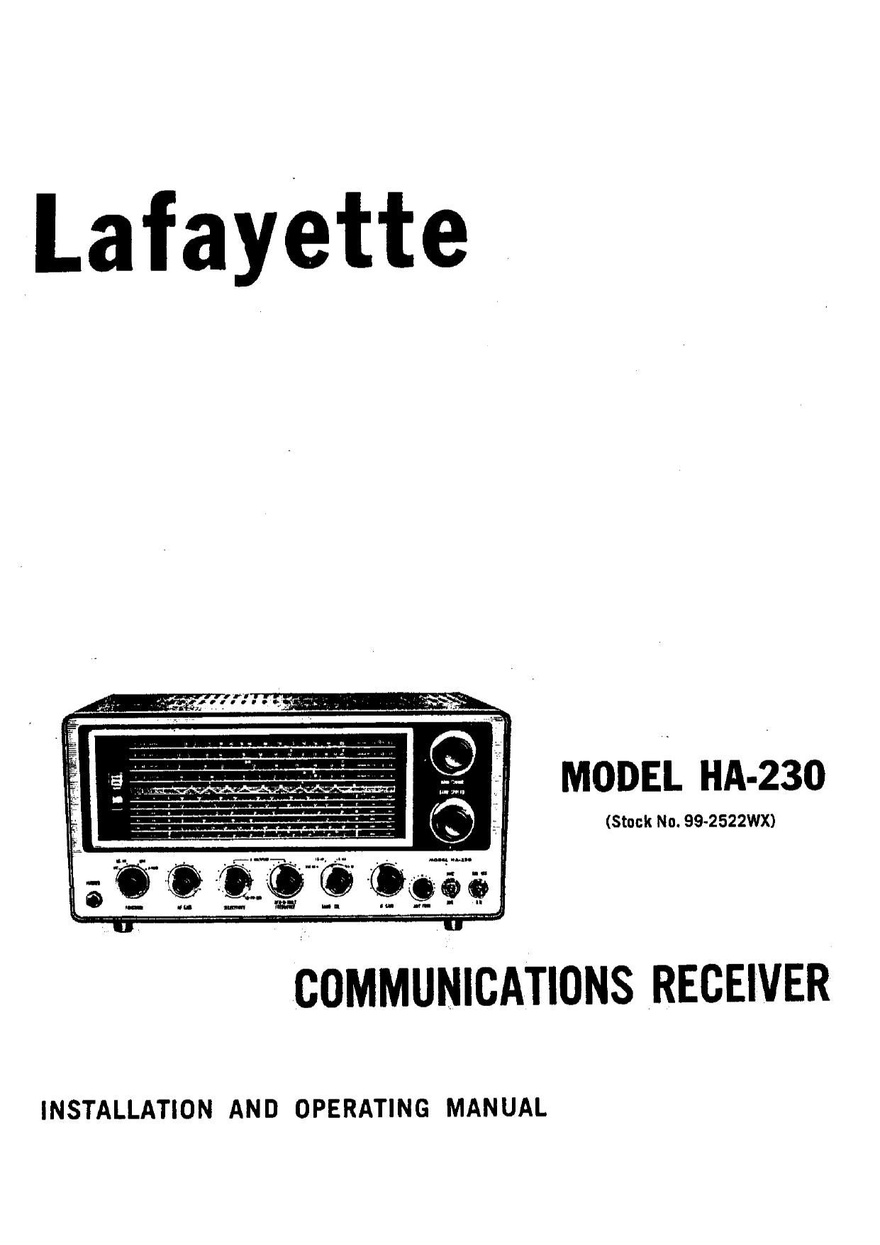
Lafayette

MODEL HA-230

(Stock No. 99-2522WX)

INSTALLATION AND OPERATING MANUAL

Page 4

i-_50 lOQFT h-T

-D___.___¢_-p_

_@ (o; E?) TO GROUND
OPTIONAL
Al A: r

l-L Faeri:-L-q

FREQUENCY Mi:

75 OHM
TWIN WIRE

Al A1 I'
0 @J0 GROUND
OPTi ONAL

Figure 1. Single Wire Antenna ilnverted L:

AUXILIARY SOCKET

T0 EXTERNAL
. SWiTCH

Figure 3. Auxiliary Control Socket

SEND position. The external switch is attached
to the 5-pin plug so that pins 3 and 2 (see Fig. 3)
will be connected when signal reception is de

Figure 2. Doublet Antenna

sired. This plug is then inserted into the socket
in place of the jumper plug. In this manner.
signal reception will be instantaneous. as plate
voltage will be applied to the RF stages when
the switch is closed accordingly.

For normal operating conditions With no ex-
ternal switching, the jumper plug pronded must
be inserted into the socket. Pins 3 and 2 of the
plug are shorted, thus providing plate voltage
to the RF stages. To disable the receiver under
these conditions, sat the FUNCTION switch to
the SEND position. In this position plate voltages
to the RF stages are cutoff. Returning the switch
to REC AM will provide instantaneous signal
reception.

THE Q-MULTIPLIER CIRCUIT

A Q-Multiplier provides the additional select-
ivity often required for optimum reception of
signals in the congested short-wave bands. In
your receiver. the Q-Multiplier circuit serves a
dual function - Q-Multiplier and BFO. For
CW and SSH reception, the circuit is employed
as a BFO.

, THE CIRCUIT MAY BE EMPLOYED AS A
Q-MULTIPLIER ONLY DURING PHONE RE<
CEPTION.

A little experience in using the Q-Multiplier
will be necessary for optimum results under dif-
ferent receiving conditions. In the hands of an
experienced operator, the Q-Multiplier is a very
handly tool. and will greatly enhance the per-
formance of the receiver.

The controls associated with the Q-Multiplier

circuit are the SELECTIVITY and BFO-Q-MULT
FREQUENCY controls. They are not operative
unless the Function switch is in the Q-MULT
position.

SELECTIVITY CONTROL

When the SELECTIVITY control is in the
AM-CWaSSB position, the circuit oscillates, thus
providing the beat signal necessary for CW or
$53 reception. Off the AM-CW-SSB position.
the circuit is connected to the IF stage and now
acts as a narrow gate through which the IF
signals must pass. The width of the gate is
determined by the position of the SELECTIVITY
control. Advancing the control from the fully
counterclockwise position serves to peak the
signal increasingly until a point of oscillation is

Page 6

mum background noise, Each setting will be
good only over a limited range of frequencies.
The trimmer should therefore always be read»
justed after tuning to the general area where the
expected signal is to be found.

AM OPERATION

For the reception of broadcast stations, short-
wave listening. etc.. place all controls in the
positions indicated in the Initial Control Set
ings chart. Tune in station. usmg Main and
Baiidspread tuning controls as indicated in the
section under TUNING". Adjust ANT TRIM
for highest S" meter reading on signal. This
antenna control setting is satisfactory while ope-
rating over a limited frequency range, If exces-
sive spurious noises such as those caused by
auto ignition make reception difficult. place the
ANL OFF switch to the ON position. The auto-
matic noise limiter should be used only when
necessary. since it tends to reduce the overall
efficiency of the receiver.

If interference from nearby stations makes
reception difficult. the Q-Multiplier may be
employed to minimize or eliminate the inter-
fere" a Since the use of the Q-Multiplier results

in a narrower bandwidth it should only be
employed when interference is severe and where
maximum fidelity is not required.

CW OPERATION

The control settings required for the recep-
tion of code Signals are indicated in the chart.
AVC is switched off and the IF GAIN control
is used as a volume control. Tune signal to zero
beat. The BFO-Q-MULT FREQUENCY control
should then be adjusted on either side of white
dot for desired pitch.

SINGLE SIDE BAND OPERATION

The settings of controls for SSB reception is
essentially the same as for CW lsee chartl. The
BFO frequency however, is used in this case
for carrier reinsertion. AVC is switched off and
the IF GAIN control used to adjust the level
Tune station in with BANDSPREAD control and
then adjust BFO«Q-MULT FREQUENCY control
for clarity of speech. Slight readjustment of the
BANDSPREAD may be necessary to provide best
audio quality.

INITIAL CONTROL SETTINGS

CONTROL AM SETTINGS CW SETTINGS SSB SETTINGS

FUNCTION REC AM Q-MULT Q-MULT

BAND SEL Set for desired range Set for desired range Set for desired range

SELECTNITY AM-CW-SSB* AM-CW-SSB AM-CW-SSB

BFO-Q-MULT V

FREQUENCY Mid-position Mid-position - Mid-position

IF GAIN Maximum Adjust for desired Adjust for desired
audio level audio level

ANT TRIM 12 o'clock position 1?. o'clock position 12 o'clock position

MVC-AVC AVC MVC MVC

ANL OFF-ON Optional Optional OFF

BANDSPREAD Set to 100 on Logging Scale Set to 100 on Logging Scale Set to 100 on Logging Scale

AF GAIN Adjust for desired 2/3 to 3/4 clockwise 2/3 to 3/4 clockwise

audio level

* Setting the SELECTIVITY control to AM-CW-SSB with the FUNCTION switch in
REC AM disconnects the Q-Multiplier from the IF, allowing normal IF band pass.