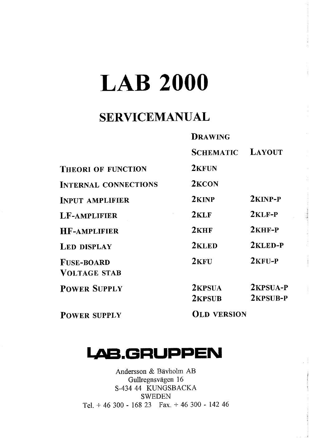
Labgruppen lab 2000 service manual

This is the 34 pages manual for labgruppen lab 2000 service manual.
Read or download the pdf for free. If you want to contribute, please mail your pdfs to info@audioservicemanuals.com.

Page: 1 / 34
left right
labgruppen lab 2000 service manual

Extracted text from labgruppen lab 2000 service manual (Ocr-read)


Page 2

LAB 2000C

Theory of function

AC-power is coming in to terminal Kl. The voltage is rectified by D1 and filtered
by C10, C11. This gives 310V DC to the transformer TR1. The PWM-controller
U1 controls the switch Q1-Q3 to give the correct output voltage at terminal J17,
J19. When the switch Q1-Q3 i closed, current flows trough transformer, TR1,
storing energy. Because of the voltagepolarity, diode D3, D4 are reverse-biased,
thus no voltage present at the load. When the switch is open, transformer TR1
reverses polarity because of the collapsing magnetic field, forward-biasing diod D3,
D4, and inducing a current flow into the capacitors C12, C14. The reversed voltage
is sensed by a winding in TR1 and rectified by diod D8. The PWM-controller
adjust the on-time of the switch, by comparing the voltage across C14 with an
internal referens, to give a railvoltage of +-136V across the capacitors C12,C14.
The voltage can be adjusted by potentiometer TPZ. The maximum current in the
transformer is sensed over the resistor R6-R8. The voltage across R6-R8 is
compared with a referense-voltage, set by TP3, which make it possible to adjust the
maximum output power from the powersupply. Normally TP3 is in maximum
position, but if something has too be repaird in the amplifier, TP3 is used for
"slowstarting" the amplifier.

The inputsignal is connected to the balanced amplifier U1. The gain in this
amplifier can be reduced by optoresistor LDRl to prevent clipping in the output
amplifier. From amplifier U1 signal is going to limiter U2, Q1, Q2 passing
gaincontrol P]. This limiter together with the phaselineare lowpassfilter U3, U4
limits the slewrate of the signal going to the output amplifier ZKLF, preventing
intermodulation in this amplifier if signals of too high frequencies are presented on
the input terminal.

The output amplifier ZKLF works as an ordinary power amplifier with the
difference that the collectorvoltage to the output transistors is supplied from the
switchmode amplifier ZKHF. The base voltage on the output transistors Q26-Q28,
Q31-Q33 is sensed by voltage divider R36-R38 and is then sent to the adjustable
limiter U3, U4 on the input board, bofore it reaches the input on the switchmode
amplifier. Limitlevel is set by the minimum load select-switches (MLS-sv.) to give
correct output power in different loads.

The amplifier U1 (U2) on the HIP-board makes sure that the output signal on
terminal J4 (18) is a copy of the input signal on terminal J12, by giving correct
controvoltage to pulsewidth modulator U3. U3 compares this voltage with an
830Khz triangularwave giving a pulsewide modulated output signal from Q1 (Q7)
which is filtered by L1, C1 (L4, C10). The gain from the base of the output
transistors in the LF-amplifier to the output of the HF-amplifier is equal to one.
TPI (TPZ) is used to add a DC-ofsett on the input of U1 (U2) giving +11V (J4) -
11V (J8) relative output of the LF-amplifier (J6), which is the same as collector-
emitter voltage for the output transistors Q26-Q28, Q31-Q33.