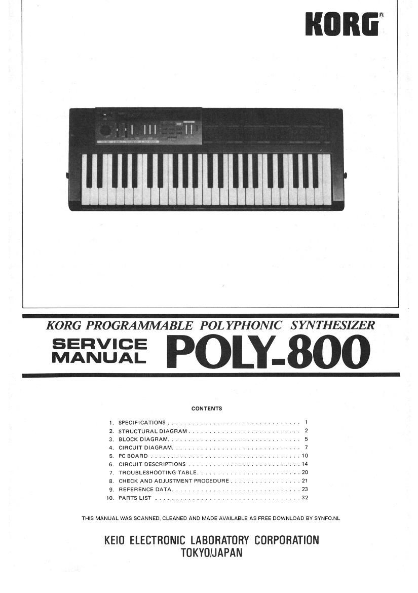
KORG POLY 800 SERVICE MANUAL

This is the 40 pages manual for KORG POLY 800 SERVICE MANUAL.
Read or download the pdf for free. If you want to contribute, please mail your pdfs to info@audioservicemanuals.com.

Page: 1 / 40
left right
KORG POLY 800 SERVICE MANUAL

Extracted text from KORG POLY 800 SERVICE MANUAL (Ocr-read)


Page 1

me

uuuuumuuuumu

KORG PROGRAMMABLE POL YPHONIC S HVT HESIZER

fiififlfifi POLY-800

CONTENTS
1 SPECIFICATIONS ............................... 1
2. STRUCTURAL DIAGRAM ........................... 2
3. BLOCK DIAGRAM ............................... 5
4. CIRCUIT DIAGRAM ............................... 7
5 PC BOARD .................................... 10
6. CIRCUIT DESCRIPTIONS ........................... 14
7. TROUBLESHOOTING TABLE ......................... 20
8. CHECK AND ADJUSTMENT PROCEDURE ................. 21
9. REFERENCE DATA ............................... 23
10. PARTS LIST ................................... 32

THIS MANUAL WAS SCANNED. CLEANED AND MADE AVAILABLE AS FREE DOWNLOAD BY SYNFO.NL

KEIO ELECTRONIC LABORATORY CORPORATION
TOKYOIJAPAN

Page 2

1.

SPECIFICATIONS

Keyboard
Voice

DCOI

DCO2

DCO Mode
Noise
VCF

Chorus
DEG1 (FOR
DCOI)

DEGZ (FOR
DCOZ)

DEGB (FOR
VCF & NOISE)

MG
MIDI
TUNE
Power
Joystick
Bend

Sequencer

49 keys (C-C), Normal or Reverse
Color

8 Voice (WHOLE mode)

4 Voice (DOUBLE mode)

Octave (LOW, MID, HIGH), Waveform
(l\ , FL),16' 84' 2' (ON/OFF)
Level (0 - 31)

Octave (LOW, MID, HIGH), Waveform
\t I-L ). 16' 84' 2' (ON/OFF)
Level adjustment, Interval (0 - 12
semitones), Detune (-20 cents MAX)
(WHOLE, DOUBLE)

Level (0 - 15) (White noise)

Cutoff Frequency (0 - 99), Resonance
(0 - 15), Keyboard Track (OFF, HALF,
FULL), EG Intensity (0- 15), EG
Polarity (Vs /\), Trigger mode (for
DEG3 only) (SINGLE, MULTII
ON/OFF

Attack time, Decay time, Break Point
level, Slope time,Sustain level,
Release time (ALL 0 - 31).

Attack time, Decay time, Break Point
level, Slope time, Sustain level,
Release time (ALL 0 - 31).

Attack time, Decay time, Break Point
level, Slope time, Sustain level,
Release time (ALL 0 - 31).
Frequency, Delay time, DCO intensi-
ty, VCF intensity (ALL 0 - 15).
Receive Channel (1 - 16), Program
Change (ENABLE/DISABLE), Se-
quencer Clock (INT, EXT)

+/- 50 cents

OFF, Master VOLUME

X axis (+/- Pitch bend);

+ Y axis (DCO modulation);

- Y axis (VCF modulation)
Maximum Pitch BEND (+/-700

cents (Perfect 51h) MAX)
START/STOP, STEP, SPEED (Slow .
Fast)

Key assign
mode
Programs
Programmer

Display

Tape interface

Input jacks

Output jacks

Tape switch
Write switch

MIDI jacks
DC 9V

Strap pegs
Dimensions

Weight
Accessories

POLY, CHORD MEMORY, HOLD

64 (11 to 88)

Number select buttons (1 - 8), PRO-
GRAM/PARAMETER, BANK HOLD,
UP, DOWN, WRITE switches

Program Number, Parameter Number,
Parameter Value, Bank hold indicator,
Edit indicator

Save, Load, Verify, Cancel

FROM TAPE (HIGH/LOW), PRO-
GRAM UP (L GND)

Output (R, L/MONO), HEAD-
PHONES, TO TAPE.
ENABLE/DISABLE

Program (ENABLE/DISABLE)
Sequencer (ENABLE/DISABLE)

IN, OUT

AC adapter jack (300 mA minimum;
use only recommended KORG
adapter)

2

W: 780mm (31") x D: 286 mm
(11.25") x H: 89 mm (3.5")

4.3 kg (10 lbs) (including batteries)
AC 9V adapter, Cassette tape of Fac-
tory Preload Programs, Shielded audio
cord (2.5 m), batteries (UM-2 x 6)